Custom Firmware Example Artery
Custom firmware example - Artery
本章节说明如何创建一个兼容 Vision External Module 和 Artery controller 的 custom firmware。这里假设您已经根据 Custom Hardware chapter 完成了 custom hardware:
https://server.kk-t.eu/ExternalVision/ExampleCustomHardware
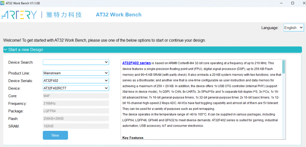
- 从 Artery website 下载 Artery Workbench:https://www.arterytek.com/file/download/1710
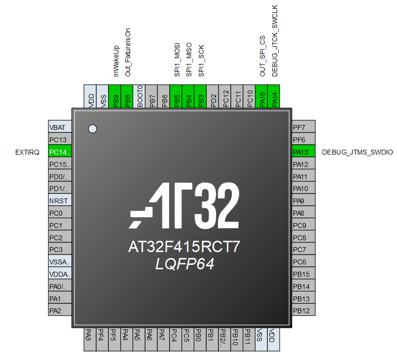
- 打开工具,并使用 selected IC 创建 new project。Example 使用 AT32F415RCT7。
- 创建两个相同 projects:一个用于 Bootloader,一个用于 Application,并分别命名。
配置 hardware interface
按照您的 schematics,将 interface 连接到 Vision Controller。以下 pins 应配置:
- IRQ as GPIO ExtInt,使用 both edges interrupt
- Fixture_Is_On as GPIO Output
- Main_Wake_Up as GPIO Input
- SPI_CS as GPIO Output
- SPI_MISO as SPI MISO
- SPI_MOSI as SPI MOSI
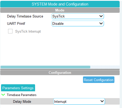
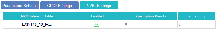
Library 需要 time base,因此必须 enable SysTick in interrupt mode。IRQ 应配置为 EXINT mode,并且 interrupt priority 必须很高。按照 Vision SPI library 的要求,IRQ priority 保持在 Priority 0。
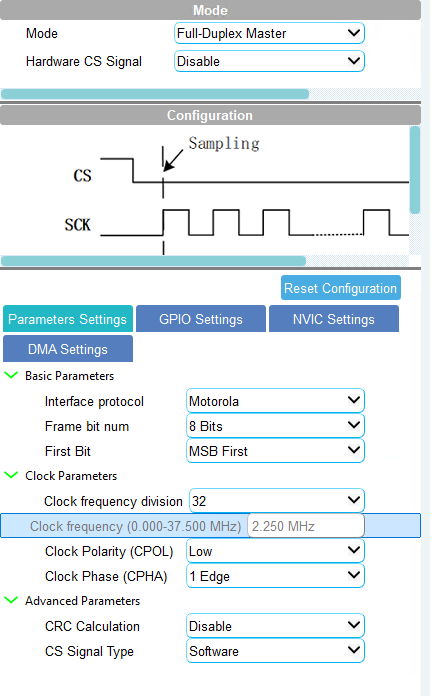
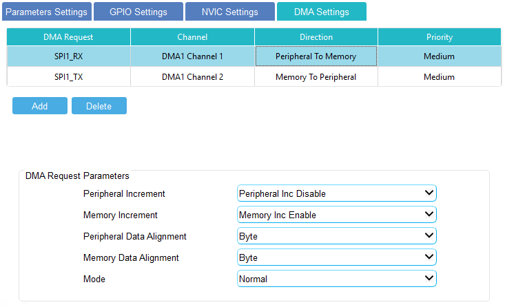
SPI 应配置为 Full Duplex Master。Clock frequency 不需要太高;按照 library documentation 选择 moderate clock frequency 即可。如果 IC 支持 DMA,建议使用 DMA 以节省 CPU resources。SPI IRQ 和 DMA Channel IRQ priority 可设置为 1,以保证 IRQ EXTI 优先级更高。Minimum heap size 至少设置为 0x400。
集成 libraries
下载 example project:
https://server.kk-t.eu/ExternalVision/ExampleSoftware
下载后建议使用 WinRAR extract。建议同时阅读 Vision SPI Library 和 Vision RDM Library documentation:
https://server.kk-t.eu/ExternalVision/SPIInterfaceVision
https://server.kk-t.eu/ExternalVision/RDMLibrary
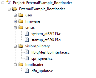
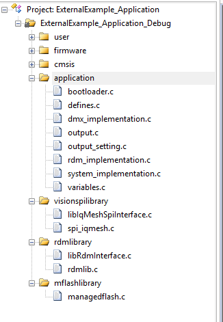
将 Bootloader 和 Application folders 复制到 project structure 中。同时复制 Vision SPI Library (SPI_V3)、Vision RDM Library (RDM) 和 managedFlash library。
Bootloader project
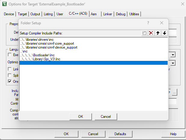
打开为 KEIL IDE 生成的 Bootloader Project,添加 SPI library 和 DFU 需要的 source files,并 include 必要 header files。
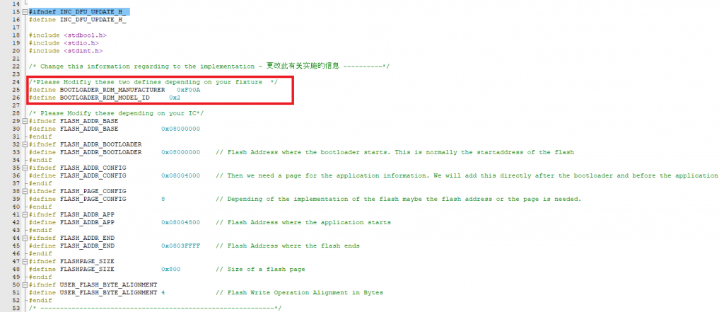
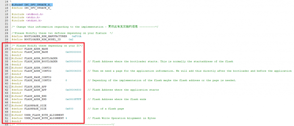
修改 dfu_update.h,使其适配您的 custom project。RDM-related defines 必须根据 product 的 RDM definition 设置;如果没有 RDM definition,请联系我们。Flash defines 也必须根据您的 flash layout 修改,并限制 bootloader 可使用的 flash size,避免 bootloader 超出 reserved flash area。
在 main.c 中 include DFU header。初始化前调用 DfuCheckBootReason,初始化完成后调用 DfuDownloadFlash。随后实现 dfu_update.h 中声明的 external hardware functions,例如 HardwareEraseFlash、HardwareWriteFlash、SPI CS pin、IRQ pin、FixtureIsOn pin、time base 和 SPI transfer function。
Application project
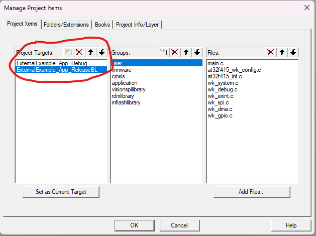
Application project 的方法基本相同:添加 application 所需 source files 和 header paths。创建 Debug target(without bootloader)和 ReleaseBL target(与 bootloader 一起工作)。然后根据 hardware 设置必要 preprocessor defines。
| USER_FLASH_ADDRESS | Start of the Flash |
| USER_FLASH_START | Start of the Flash where the settings will be saved. Address after the application |
| USER_FLASH_SIZE | Flash area used for settings |
| USER_FLASH_PAGE_SIZE | Size of the flash pages |
| USER_STORAGEOBJECTS | Count of storage objects saved using managed flash library |
| USER_FLASH_BYTEALIGNMENT | Flash write operation alignment in bytes |
| USER_FLASH_ADDRESS_CONFIG (Release Only) | Flash address where application information from bootloader is saved |
| USER_FLASH_ADDRESS_APP (Release Only) | Flash address where application starts |
#DEBUG
DEBUG
USER_FLASH_ADDRESS = 0x08000000
USER_FLASH_START = 0x08003B000
USER_FLASH_SIZE = 0x5000
USER_FLASH_PAGE_SIZE = 0x800
USER_STORAGEOBJECTS = 7
USER_FLASH_BYTEALIGNMENT = 4

#RELEASE_BOOTLOADER
RELEASEBL
USER_FLASH_ADDRESS = 0x08000000
USER_FLASH_START = 0x0800E400
USER_FLASH_SIZE = 0x5000
USER_FLASH_PAGE_SIZE = 0x800
USER_STORAGEOBJECTS = 7
USER_FLASH_BYTEALIGNMENT = 4
USER_FLASH_ADDRESS_CONFIG = 0x08004000
USER_FLASH_PAGE_CONFIG = 8
USER_FLASH_ADDRESS_APP = 0x08004800
启动时如果使用 bootloader,请确保重新分配 vector table,并 reset 必要 configuration。Peripheral initialization 后初始化 system,并使用 timestamp in milliseconds 调用 SystemTask。
然后按需要修改 example system。Example 中包含 button interface 等内容,在 custom project 中可能不需要,可以删除 unnecessary code,并直接进入 system state normal。请根据 App Control 所需 DMX footprint 修改 vision_init 的 value。通常 App Control 需要 full control over all LEDs and in 16 bit,因此这个 footprint 通常是最长 DMX footprint。该 value 可以更长,但不应更短。
项目应能 build successfully。之后请根据您的 product 修改 defines.c 和 defines.h,修改 dmx_implementation.c 以匹配 product 的 DMX implementation,并在 rdm_Implementation.c 中 adapt RDM commands。
完成后请继续 Test Preparations:
https://server.kk-t.eu/ExternalVision/TestPreparations
Full custom project download:
https://kk-t.com/wp-content/uploads/2026/05/VisionExternalExample_CustomProject_2026_05_22.zip
如果 Main IC 与 Vision IC communication 有问题,请参考 step by step debug guide:
https://kk-t.com/wp-content/uploads/2025/08/iqMeshIntegration_DebugGuide.pdf
分析 Vision Wireless Controller logs
可 flash special firmware 到 Vision Wireless Controller,以 enable 并查看 logs。这些 logs 对 implementation process 很有帮助。该 firmware 仅用于 development,不得用于 serial/production units。
- Fanstel BT840 (nrf52840): On request
- Wuerth Orphelia III / Proteus III (nrf52840): On request
- Fanstel BC833 (nrf52833):
https://server.kk-t.eu/api/v1/share/File?file=DEBUG_VISIONCONTROLLER_VISION_SPI_FBC833_APP5_6_3_SD_7_3_0_DEBUG_SPI_INTERFACE.bin - Abluetech PTR9818 (nrf52840): On request
- Abluetech PTR9813/PTR9813+ (nrf52833):
https://server.kk-t.eu/api/v1/share/File?file=DEBUG_VISIONCONTROLLER_VISION_SPI_FBC833_APP5_6_3_SD_7_3_0_DEBUG_SPI_INTERFACE.bin
WARNING: Dev only. Never flash on serial/production units.
- Open SEGGER J-Flash
- Select your controller(documentation example uses nRF52833)
- Load the special firmware file from above
- Click Erase Chip
- Click Program Device
- Open J-Link RTT Viewer
- Review the logs of the Vision Wireless Controller