Custom Firmware Example STM32
Custom firmware example - STM32
本章节说明如何创建一个兼容 Vision External Module 和 STM32 controller 的 custom firmware。这里假设您已经根据 Custom Hardware chapter 完成了 custom hardware:
https://server.kk-t.eu/ExternalVision/ExampleCustomHardware
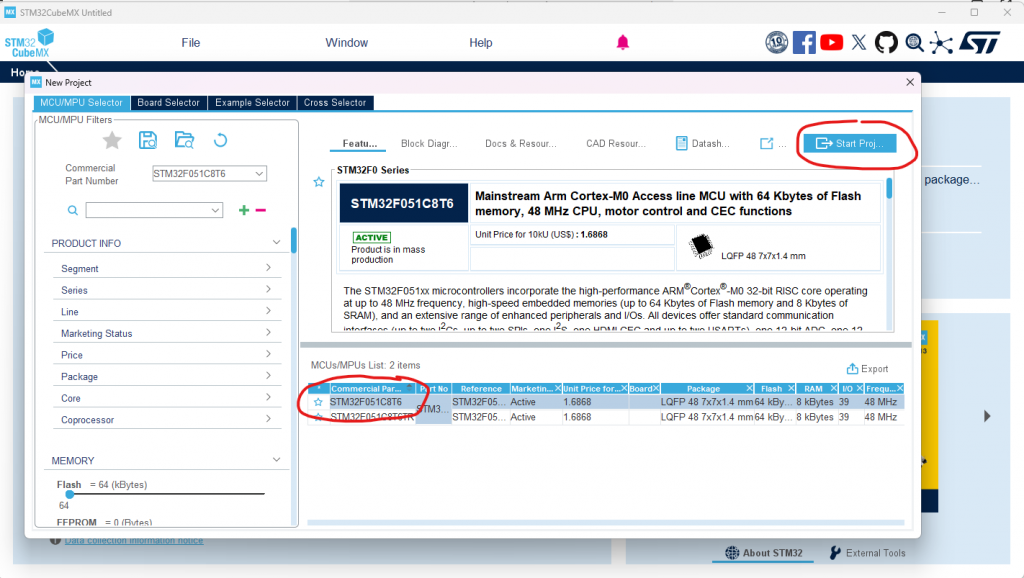
- 下载 STM32 Cube MX,或使用 STM32Cube IDE:https://www.st.com/en/development-tools/stm32cubemx.html
- 使用 selected IC 创建 new project。Example 使用 STM32F051。
- 创建两个相同 projects:一个用于 Bootloader,一个用于 Application,并分别命名。
配置 hardware interface
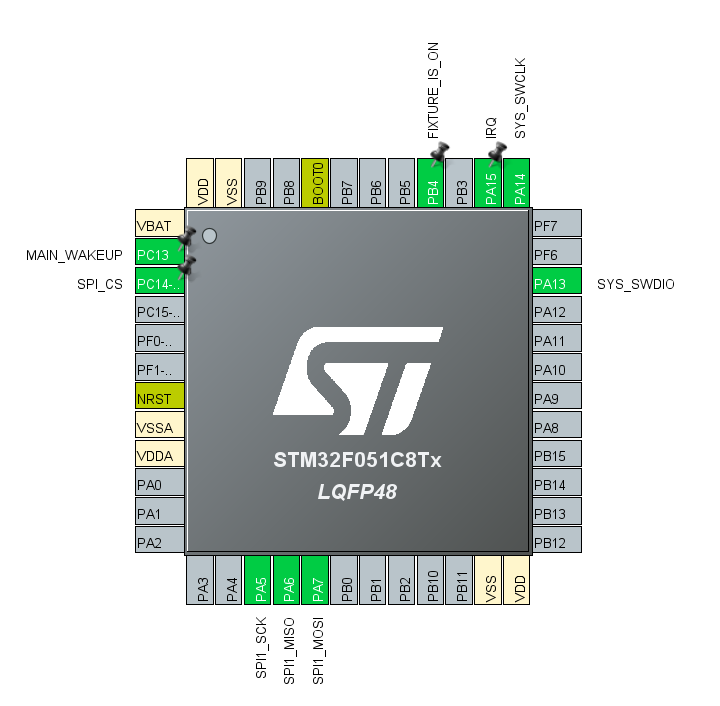
按照您的 schematics,将 interface 连接到 Vision Controller。以下 pins 应配置:
- IRQ as GPIO ExtInt,使用 interrupt with both edges
- Fixture_Is_On as GPIO Output
- Main_Wake_Up as GPIO Input
- SPI_CS as GPIO Output
- SPI_MISO as SPI MISO
- SPI_MOSI as SPI MOSI
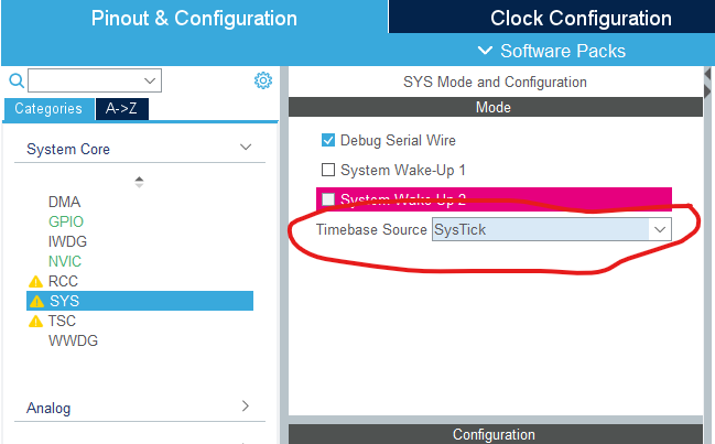
您可以根据需要完成 clock configuration 等内容。这里重点说明 Vision interface 所需 peripherals。
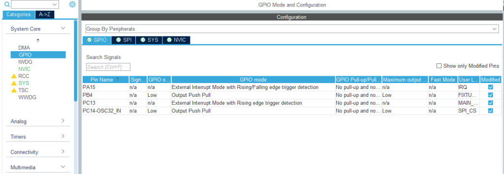
在 System Core Settings 中确认使用 SysTick Event。然后在 GPIO section 中正确配置 IRQ pin 和其他 GPIOs。IRQ 必须使用 External Interrupt Mode with Rising/Falling edge trigger detection。MainWakeUp 可根据需要配置;如果 main IC 支持 sleep mode,可通过 Vision module wake up main IC。刚开始熟悉 platform 时通常不需要使用该 pin。
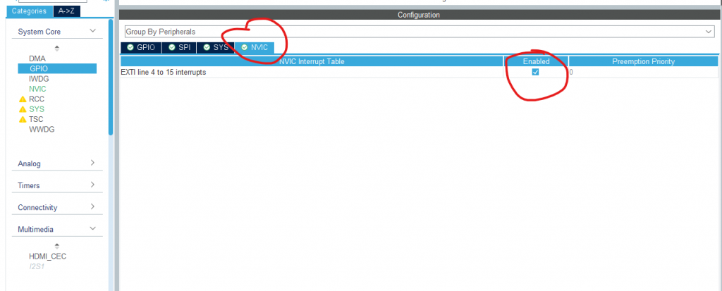
Enable required interrupt through NVIC。按照 Vision SPI library 的说明,IRQ pin 必须具有很高 priority,因此保持 Priority 0。SPI 和 DMA interrupts 可设置为 Priority 1,以免影响 IRQ pin interrupt。
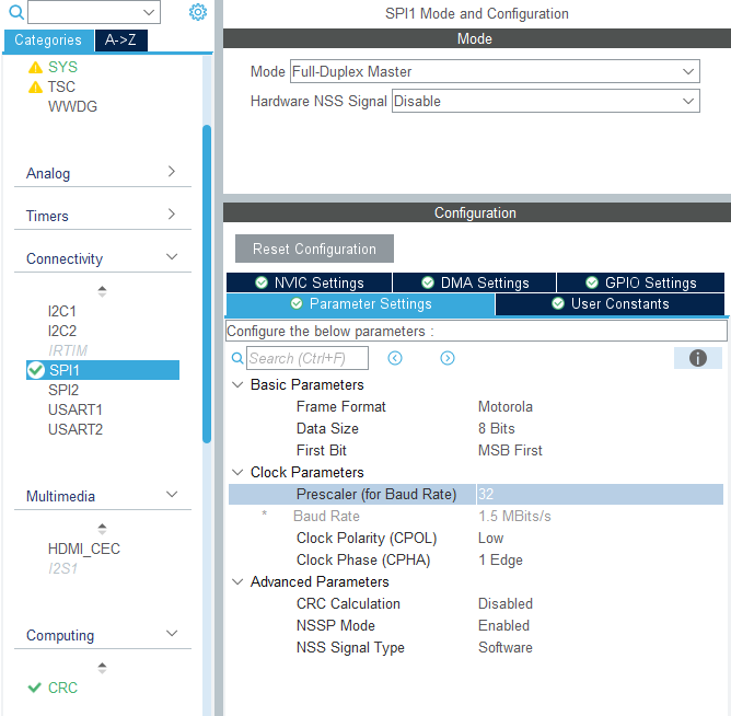
SPI configuration:
- Full Duplex Master
- Moderate clock frequency
- Frame Format Motorola
- Data Size 8 Bits MSB First
- CPOL Low
- CPHA 1 Edge
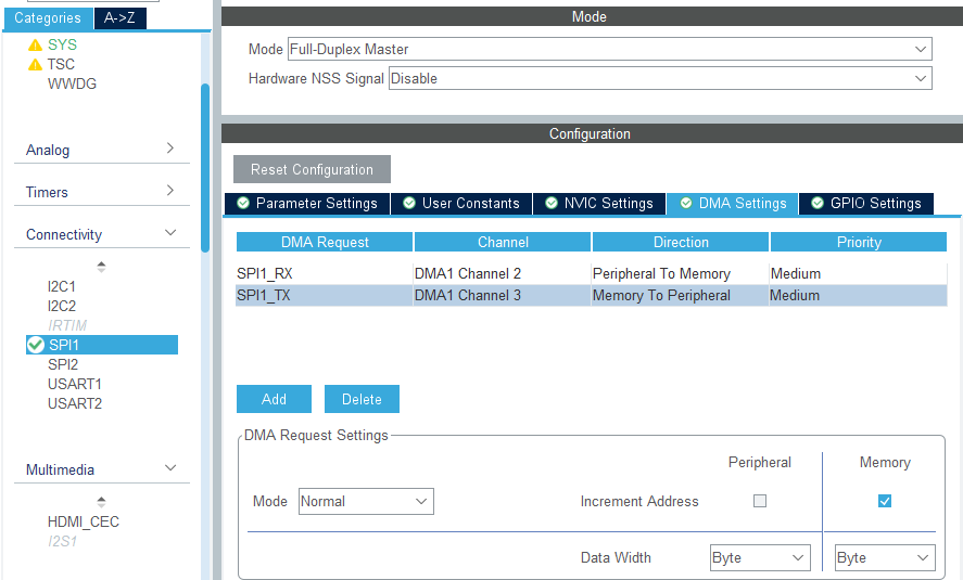
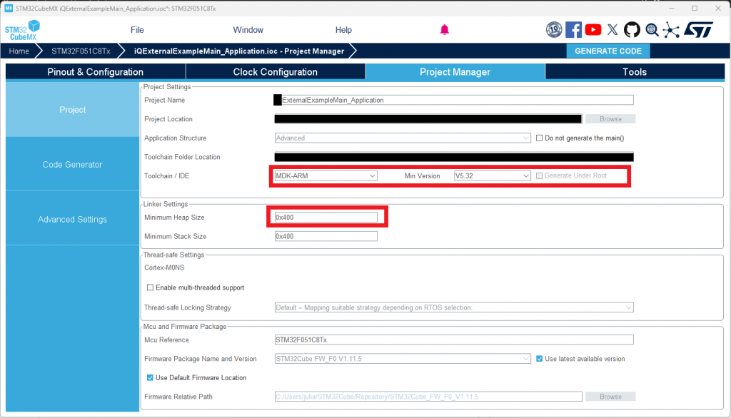
如果 IC 支持 DMA,建议使用 DMA 以节省 CPU resources。然后 enable SPI 和 DMA interrupts。Minimum heap size 至少设置为 0x400,并选择正确 Toolchain/IDE;example 使用 KEIL MDK Arm V5。
生成并集成 libraries
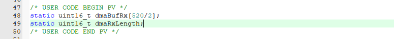
Generate Code 后,会得到 Application project 和 Bootloader project。两个 project 使用相同的基础 modifications。首先在 main.c 中实现 hardware functions,并定义 SPI RX buffer。Buffer 应为 520 Bytes,并根据 implementation 进行 16 bit alignment。
下载 example project:
https://server.kk-t.eu/ExternalVision/ExampleSoftware
建议同时阅读 Vision SPI Library 和 Vision RDM Library documentation:
https://server.kk-t.eu/ExternalVision/SPIInterfaceVision
https://server.kk-t.eu/ExternalVision/RDMLibrary
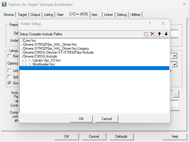
将 Bootloader 和 Application folders 复制到 project structure 中。同时复制 Vision SPI Library (SPI_V3)、Vision RDM Library (RDM) 和 managedFlash library。
Bootloader project
打开为 KEIL IDE 生成的 Bootloader Project,添加 SPI library 和 DFU 需要的 source files,并 include 必要 header files。

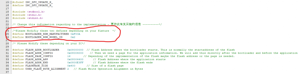
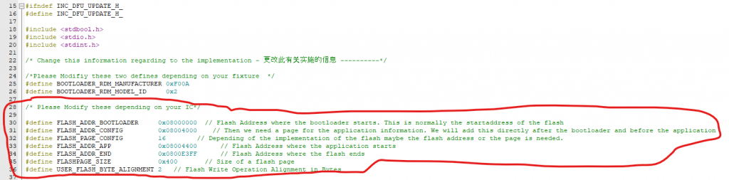
修改 dfu_update.h,使其适配 custom project。RDM-related defines 必须根据 product 的 RDM definition 设置;如果没有 RDM definition,请联系我们。Flash defines 必须根据 flash layout 修改,并限制 bootloader 可使用的 flash size。
在 main.c 中 include DFU header。初始化前调用 DfuCheckBootReason,初始化完成后调用 DfuDownloadFlash。随后实现 dfu_update.h 中声明的 external hardware functions,例如 flash erase/write、SPI CS pin、IRQ pin、FixtureIsOn pin,以及 HardwareVisionSpiSetTxRx DMA transfer function。
Application project
Application project 的方式基本相同:添加 application source files 和 header paths。创建 Debug target(without bootloader)和 ReleaseBL target(与 bootloader 一起工作)。然后根据 hardware 设置 flash start address、flash length 和 preprocessor defines。
| USER_FLASH_ADDRESS | Start of the Flash |
| USER_FLASH_START | Start of the Flash where settings will be saved. Address after the application |
| USER_FLASH_SIZE | Flash area used for settings |
| USER_FLASH_PAGE_SIZE | Size of the flash pages |
| USER_STORAGEOBJECTS | Count of storage objects saved using managed flash library |
| USER_FLASH_BYTEALIGNMENT | Flash write operation alignment in bytes |
| USER_FLASH_ADDRESS_CONFIG (Release Only) | Flash address where application information from bootloader is saved |
| USER_FLASH_ADDRESS_APP (Release Only) | Flash address where application starts |
#DEBUG
DEBUG
USER_FLASH_ADDRESS = 0x08000000
USER_FLASH_START = 0x0800E400
USER_FLASH_SIZE = 0x1C00
USER_FLASH_PAGE_SIZE = 0x400
USER_STORAGEOBJECTS = 7
USER_FLASH_BYTEALIGNMENT = 2

#RELEASE_BOOTLOADER
RELEASEBL
USER_FLASH_ADDRESS = 0x08000000
USER_FLASH_START = 0x0800E400
USER_FLASH_SIZE = 0x1C00
USER_FLASH_PAGE_SIZE = 0x400
USER_STORAGEOBJECTS = 7
USER_FLASH_BYTEALIGNMENT = 2
USER_FLASH_PAGE_CONFIG = 16
USER_FLASH_ADDRESS_APP = 0x08004400
USER_FLASH_ADDRESS_CONFIG = 0x08004000
如果使用 bootloader,startup 时请确保 relocate vector table,并 reset necessary configurations。Peripheral initialization 后初始化 system,并使用 timestamp in milliseconds 调用 SystemTask。
接下来按 product needs 修改 example system。删除不需要的 button interface,直接进入 system state normal。根据 App Control 所需 DMX footprint 修改 vision_init value。通常 App Control 需要 full control over all LEDs and in 16 bit,因此 footprint 通常是最长 DMX footprint。该 value 可以更长,但不应更短。
然后修改 defines.c 和 defines.h,修改 dmx_implementation.c 以匹配 product 的 DMX implementation,并在 rdm_Implementation.c 中 adapt RDM commands。
完成后请继续 Test Preparations:
https://server.kk-t.eu/ExternalVision/TestPreparations
Full custom project download:
https://kk-t.com/wp-content/uploads/2026/05/VisionExternalExample_CustomProject_2026_05_22.zip
如果 Main IC 与 Vision IC communication 有问题,请参考 step by step debug guide:
https://kk-t.com/wp-content/uploads/2025/08/iqMeshIntegration_DebugGuide.pdf