




Abluetech PTR9813/PTR9813+
Shenzhen Abluetech Technology Co. LTD 联系人:
May Cat
Shenzhen Abluetech Technology Co. LTD
Web: www.abluetech.com
Email: maycat@abluetech.com
PH/WA: +8618682464199
The following circuit shows a example implementation for the Abluetech PTR9813 Module. Each pin and its functionality is described in the table below.
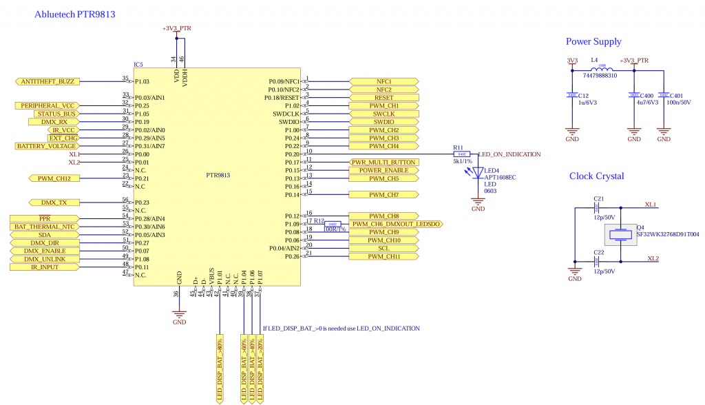
请不要更改元件和数值。请确保 +3.3V_Mesh 电源稳定,且最小供电能力为 20 mA。
请确保电容尽可能靠近 controller 连接。
| Pin | 说明 | 必需 | 功能 | 用途 | 接线 | |
| P0.04 | SCL | 否 | 用于 motion、battery charge controller、battery gauge 和 display 等 peripherals 的 I2C Clock | Pull Up (4k7) | ||
| P0.05 | SDA | 否 | 用于 motion、battery charge controller、battery gauge 和 display 等 peripherals 的 I2C Data | Pull Up (4k7) | ||
| P0.11 | IR_INPUT | 否 | IR Sensor Input for IR Remote. Output from IR Sensor. For Example: IRM-H6XXT/TR2 Vishay TSOP2436 | |||
| P0.15 | POWER_ENABLE | 否 | Output 输出 Turns on and off power from components needed during normal operation like LED Driver, additional controller, Motor driver, etc..Needed to make sure the current consumption while sleeping is minimal. If Battery Charge Controller is used the controller can be set to sleep instead this pin. | Pull Down (100k) | ||
| P0.17 | PWR_MULTI_BUTTON | 否 | Input 输入 Button: 开启/关闭 fixture 并解除链接 Switch: Turn fixture on/off | – | – | |
| P0.18 | RESET | 是 | Programming Reset | – | – | |
| P0.20 | STATUS_LED | 否 | Output 输出: 状态指示 LED | – | – | |
| P1.05 | STATUS BUS | 否 | UART RX for receiving additional information like battery state, etc.. You can find additional information under STATUS Interface | – | – | |
| P1.09 | PWM_CH6_DMXOUT_LEDSDO | 否 | Output Multiple Functions: PWM Channel 6 DMX Out (TX) LED SDO (WS2812) | – | – | |
| P0.02 | IR_VCC | 否 | Output 输出: IR Sensor 的可切换供电电压 (Needed for IR Remote) | – | – | |
| P0.09 | NFC1 | 否 | NFC Antenna | – | – | |
| P0.10 | NFC2 | 否 | NFC Antenna | – | – | |
| P0.29 | /E/X/T/_/C/H/G | 否 | Battery Management 电池管理: Charging indication Input 输入 Is only used if no battery charge controller is used and battery functions are available | Low: Charging High: No charging | – | |
| P0.28 | /P/P/R | 否 | Input 输入: Battery Management 电池管理: Power Presence Is mandatory if battery functions are necessary | Low: Power available High: No power –> battery powered | – | |
| P0.30 | BAT_THERMAL_NTC | 否 | Input 输入: Battery Management 电池管理: Battery NTC | Connect NTC using resistor divider. The resistance combination can be selected in firmware | – | |
| SWDIO | SWDIO | 是 | SWD Programming Data | – | – | |
| SWCLK | SWCLK | 是 | SWD Programming Clock | – | – | |
| P1.02 | PWM_CH1 | 否 | PWM Output Channel 1 | – | – | |
| P1.00 | PWM_CH2 | 否 | PWM Output Channel 2 | – | – | |
| P0.24 | PWM_CH3 | 否 | PWM Output Channel 3 | – | – | |
| P0.22 | PWM_CH4 | 否 | PWM Output Channel 4 | – | – | |
| P0.13 | PWM_CH5 | 否 | PWM Output Channel 5 | – | – | |
| P0.14 | PWM_CH7 | 否 | PWM Output Channel 7 | – | – | |
| P0.12 | PWM_CH8 | 否 | PWM Output Channel 8 | – | – | |
| P0.08 | PWM_CH9 | 否 | PWM Output Channel 9 | – | – | |
| P0.06 | PWM_CH10 | 否 | PWM Output Channel 10 | – | – | |
| P0.26 | PWM_CH11 | 否 | PWM Output Channel 11 | – | – | |
| P0.21 | PWM_CH12 | 否 | Optional PWM Output Channel 12 | – | – | |
| P0.25 | PERIPHERAL_VCC | 是 | Output 输出: Use this as a switch for 3V3 supply for example for the NTC | |||
| P0.31 | BATTERY_VOLTAGE | 否 | Input 输入: 如果需要 battery functions 但未使用 battery gauge,可使用该输入进行粗略 battery state measurement。不要将 BATTERY_VOLTAGE 直接连接到电池,必须通过 resistor divider 连接。 | Battery + -> 240k -> BATTERY_VOLTAGE -> 470k -> GND 100nF 从 BATTERY_VOLTAGE 接到 GND | ||
| P0.19 | DMX_RX | 否 | DMX for DMX /RDM Support | |||
| P0.23 | DMX_TX | 否 | DMX TX for DMX /RDM Support | |||
| P0.27 | DMX_DIR | 否 | Output 输出: Direction RS485 for DMX /RDM Support | |||
| P0.07 | DMX_ENABLE | 否 | DMX Enable/ Disable (Save power) | |||
| P1.08 | DMX_UNLINK | 否 | DMX Unlink for WDMX/ CRMX which is connected via Uart | |||
| P1.01 | LED_DISPLAY_BAT_>80% | 否 | Display battery LED > 80% | |||
| P1.04 | LED_DISPLAY_BAT_>60% | 否 | Display battery LED > 60% | |||
| P1.06 | LED_DISPLAY_BAT_>40% | 否 | Display battery LED > 40% | |||
| P1.07 | LED_DISPLAY_BAT_>20% | 否 | Display battery LED > 20% |
应使用以下组件:
- Abluetech PTR9813 or PTR9813+
- Crystal „EPSON FC-135 32.7680KA-AC0“ or „SF32WK32768D91T004“