




输入接口
Input interface 用于向 Vision Controller 发送数据。它是基于 UART 的协议,并在末尾带有 frame break。后续章节也会说明该协议。
该接口使用 250 kbit/s 的 asynchronous serial data。数据格式固定为 1 个 start bit、8 个 data bits(least significant first)、2 个 stop bits,且无 parity。
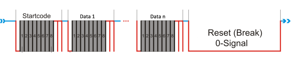
时序参数:
| Min Break (μs) | Typical Break (μs) | Min MAB (μs) | Typical MAB (μs) |
|---|---|---|---|
| 120 | 150 | 12 | 15 |
Start Code: 0xAA
Command & Data 命令与数据
数据结构包含一个 command ID field(byte)和 n 个 data fields。
| Command ID | Command Name | Data Index | Data Name | Data Description |
| 0x01 | State | 0 | Battery State / Level Indicator | 0-100: Battery available (chargeable battery for fixture operation): 1 to 100 → State of charge in %0: No battery available 255: just a small battery for wakeup and configuration of the fixture if Power Supply State is 4 or 5: 0-100 is used as Level Indicator |
| 1 | Battery Charging State / Level Indicator Info | 0: No Power (Battery wakeup) 1: Battery Powered 2: Grid Power Supply 3: Charging Battery (Not when small battery for configuration is used) If no battery but level indicator needed. For Example haze fluid level, set to one of the following: 4: Level indicator If indication for preperation needed. Like heat up, set it to: 5: Level indicator + Inpreperation | ||
| 2 | Power State | Indicates if grid power (AC) is plugged in | ||
| 0x02 | Warnings | 0 | Warning Count | Indicates the amount of Warnings |
| 1- 33 | ASCII | Space separated list of warnings in ASCII Code | ||
| 0x03 | Errors | 0 | Error Count | Indicates the amount of Errors |
| 1-33 | ASCII | Space separated list of errors in ASCII Code | ||
| 0x04 | Sensors | 0 | Sensor Index | |
| 1 | Sensor Description | |||
| 2 | Sensor Unit | |||
| 3 | Sensor Prefix | |||
| 4 | Sensor Type | |||
| 5 | Range Min Value (short) | |||
| 7 | Range Max Value (short) | |||
| 9 | Normal Min Value (short) | |||
| 11 | Normal Max Value (short) | |||
| 13 | Present Value (short) | |||
| 15 | Min Value (short) | |||
| 17 | Max Value (short) | |||
| 18- 50 | Description (32 ASCII Characters) | |||
| 0x05 | 0 | Supported Input Sources (ushort) | Bit 0: Vision Bit 1: DMX Bit 2: CRMX / WDMX Bit 3: Artnet Bit 4: SACN Bit 5: GLP DOP Bit 6: IR Remote (Fixture) Bit 7: Manual Mode Bit 8: Auto Mode Bit 9 – 15: Reserved Another Source required? Contact us Take in mind that RDM is Big Endian! So it looks like this: [Bit 8-15],[Bit 0-7] | |
| 2 | Input Source (byte) | 0: Vision, 1: DMX, 2: CRMX / WDMX, 3: Artnet, 4: SACN, 5: GLP DOP, 6: IR Remote (Fixture) 7: Manual Mode, 8: Auto Mode, 7 – 252: Reserved 253: Wireless (2.4 GHz) 254: Wireless (Other) 255: Ethernet | ||
| 3 | Input State | 0: Idle (DMX not available) 1: Unlinked (CRMX/Vision unlinked) 2: Linked (CRMX/Vision linked) 3: Active (DMX available, CRMX/Vision active signal)) 4: Vision Auto Active (Use this state only when Input Source is Auto and Vision is active sendnig data. This ensures fixture does not disable itself when VISION is sending data but disable VISION if any other source is active) | ||
| 4 | Input Quality | 0: No quality available 1-100: Quality in % | ||
| 0x06 | 0 | DMX Start Adress (ushort) | ||
| 2 | DMX Personality (byte) | |||
| 3 | DMX Personality Count (byte) | |||
| 4 | DMX Footprint (ushort) |