




Abluetech PTR9813/PTR9813+
The contact person at Shenzhen Abluetech Technology Co. LTD is:
Shenzhen Abluetech Technology Co. LTD
Web: www.abluetech.com
Email: sales@abluetech.com
Hardware implementation:
The following circuit shows an example implementation for the Abluetech PTR9813/PTR9813+ Module. Each pin and its functionality is described in the table below.
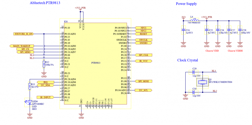
Please do not change the components and values. Ensure a stable +3.3V_Mesh supply with a minimum current delivery of 20 mA.
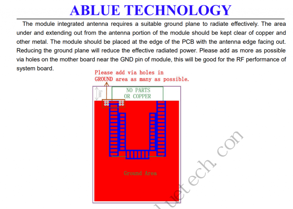
Please ensure that the capacitors are connected as close as possible to the controller and ensure a good grounding path!. For detailed PCB Layout follow the advice from the datasheet. This is important for a proper radio function!
| Pin | Description | Mandatory | Function | Use | Wiring |
| P0.03 | FIXTURE_IS_ON | Yes | Whenever this Pin is high the Vision Controller is in On State. If this Pin is low, the Vision Controller goes to sleep. If the fixture is in normal Operation (Power On) it should set this Pin to high. If the fixture is turned off, sleeping or in a wake up state this pin should be low. When the fixture wakes up due to the „MAIN_WAKEUP“ from the Vision Controller, make sure this Pin is still low! | High: Vision Controller normal operation Low: Vision Controller sleep mode | Pull Down (100K) |
| P0.02 | MAIN_WAKEUP | No | This Pin is used for signalling that the Vision Controller wants to communicate with the fixture. It is also used to wake up the main controller in order to communicate. This pin is pulled high as long the Vision Controller wants to communicate with the fixture. | This Pin is pulled high if communication is needed. Normal operation this pin is always high. | |
| P0.18 | RESET | Yes | Programming SWD | – | – |
| SWCLK | SWCLK | Yes | Programming SWD | – | – |
| SWDIO | SWDIO | Yes | Programming SWD | – | – |
| P0.31 | SPI MISO | Yes | SPI Communication Master Input Slave Output | – | – |
| P1.09 | SPI MOSI | Yes | SPI Communication Master Output Slave Input | – | – |
| P0.20 | SPI_CLK | Yes | SPI Communication Clock | – | – |
| P0.29 | SPI_CS | Yes | SPI Communication Chip Select | – | – |
| P0.30 | IRQ | Yes | SPI Communication Interrupt Signal | – | – |
| P0.09 | NFC1 | No | NFC Antenna | – | – |
| P0.10 | NFC2 | No | NFC Antenna | – | – |
| P0.04 | I2C_SCL | No | I2C Clock | – | Pull Up (10K) |
| P0.05 | I2C_SDA | No | I2C Data | – | Pull Up (10K) |
| P0.15 | IR_VCC | No | Switchable VCC for IR Sensor | In order to minimize current consumption | – |
| P0.11 | IR_INPUT | No | Output of IR Sensor | – | – |
| P0.28 | LED | No | Signal State | – | – |
| – | – |
The following components should be used:
- Abluetech PTR9813 / PTR9813+
- Crystal „EPSON FC-135 32.7680KA-AC0“ or „SF32WK32768D91T004“
Here you can download the schematic as PDF. Under the example project you can also find the Altium schematics:
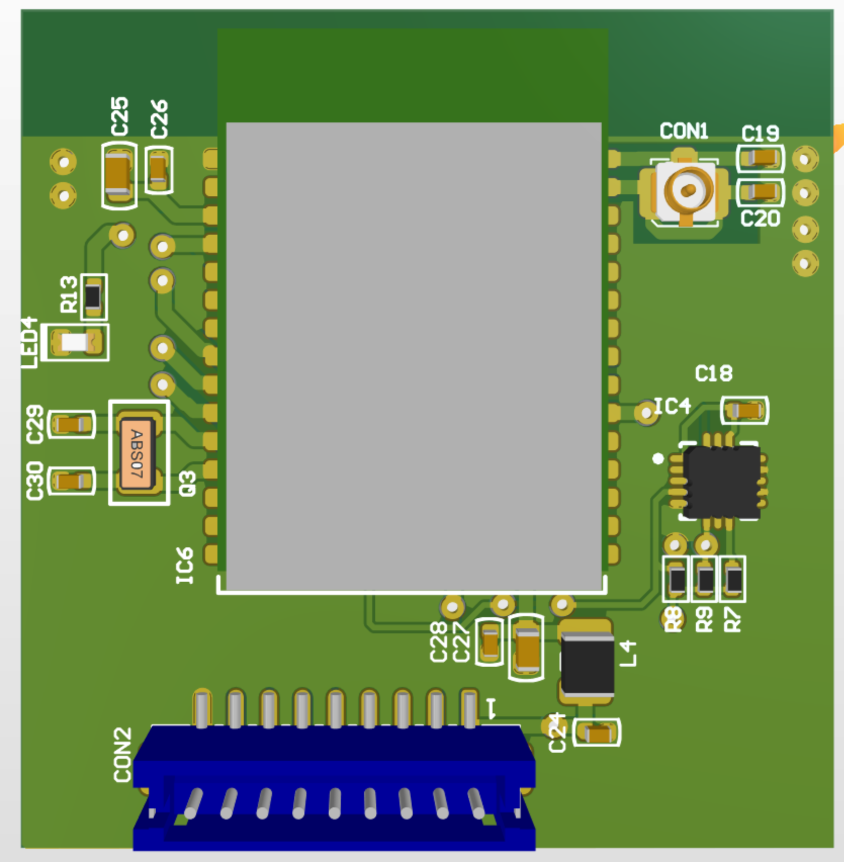
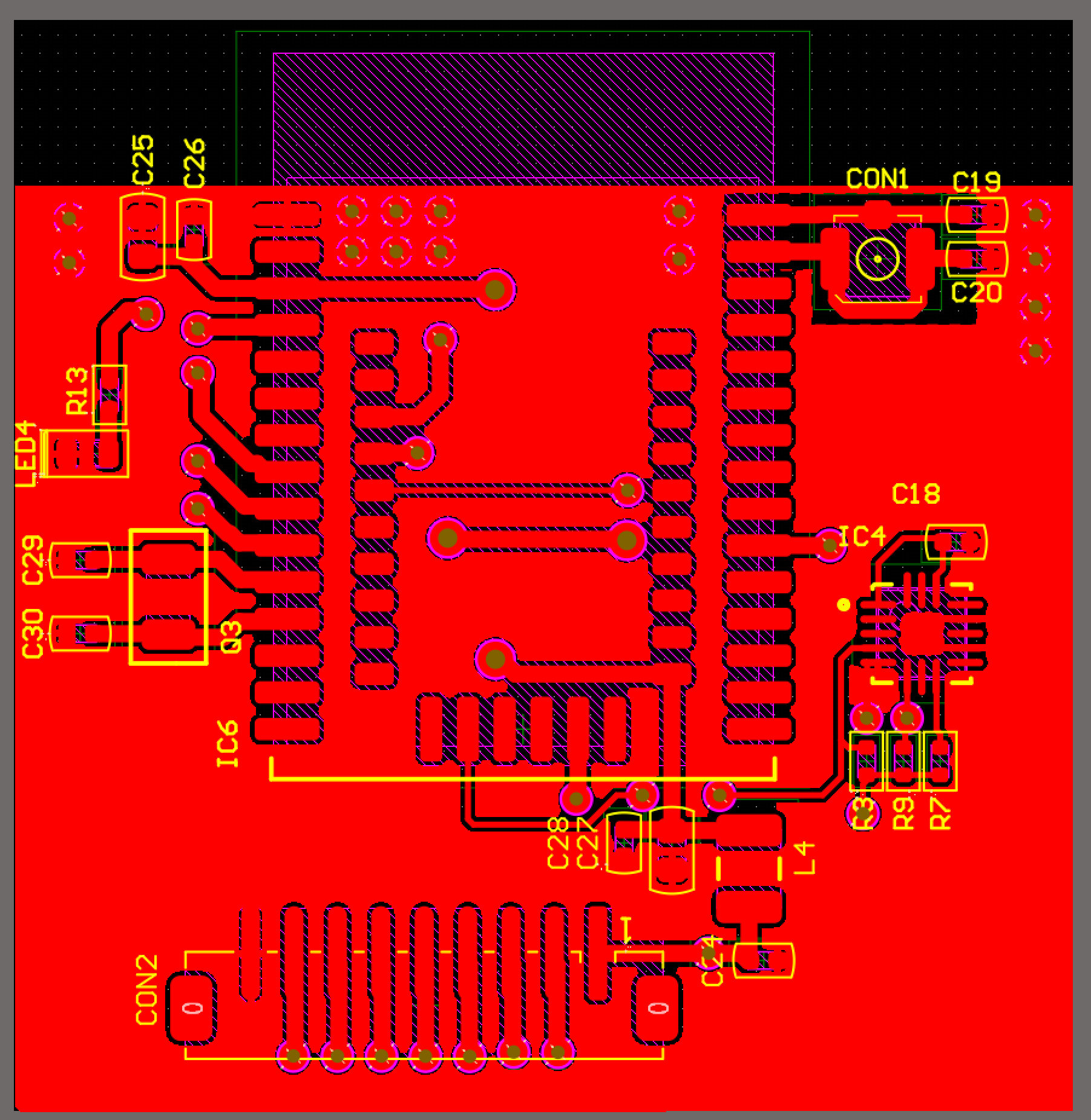
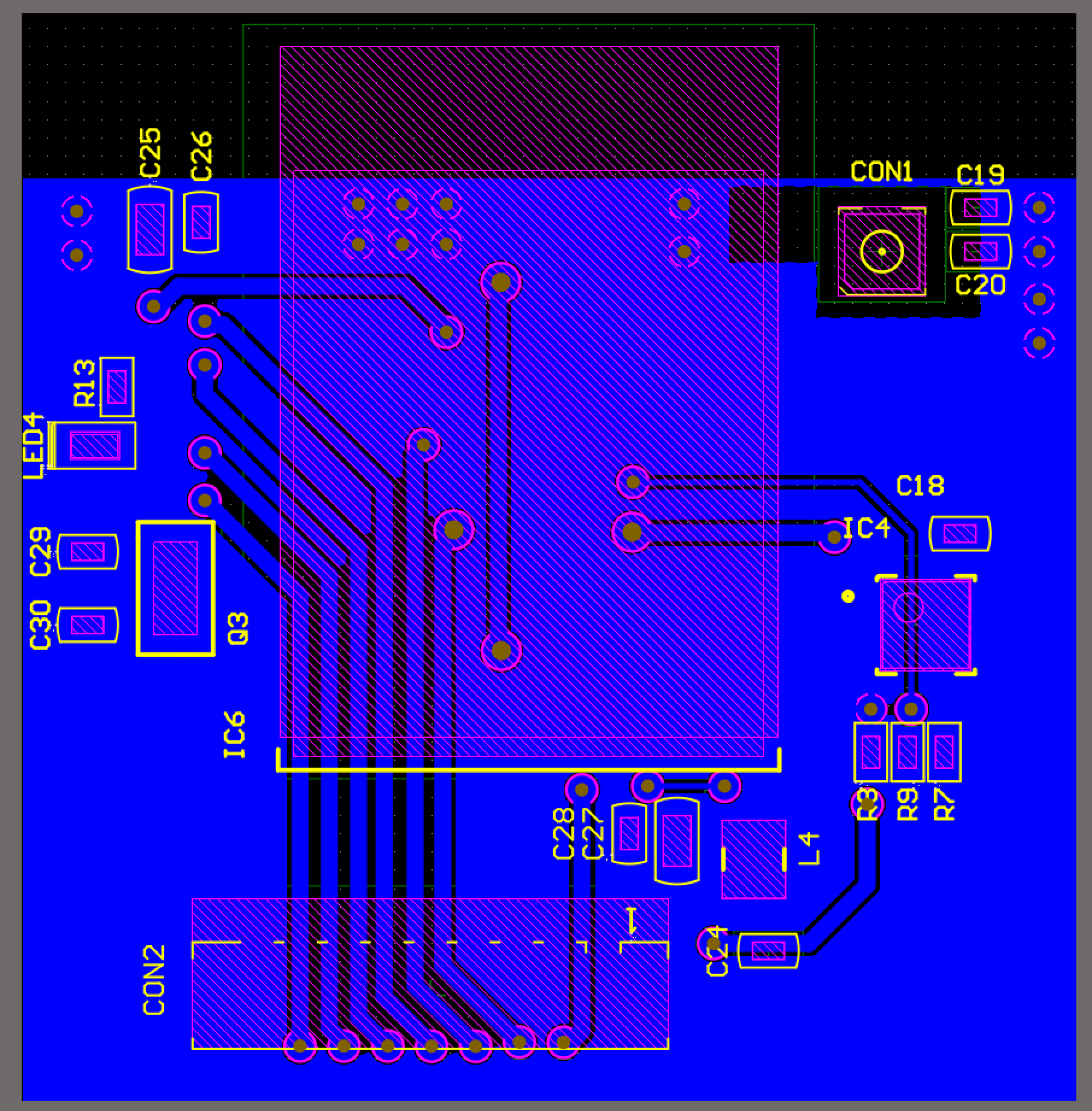
Reference PCB
A reference PCB is also available. It includes the NFC antenna and motion sensor, and it connects the important pins for I2C communication through a JST ZH connector.