




Fanstel BC833
The contact at Fanstel Corporation is:
Email: sales@fanstel.com
The following circuit shows a example implementation for the Fanstel BC833 Module. Each pin and its functionality is described in the table below.
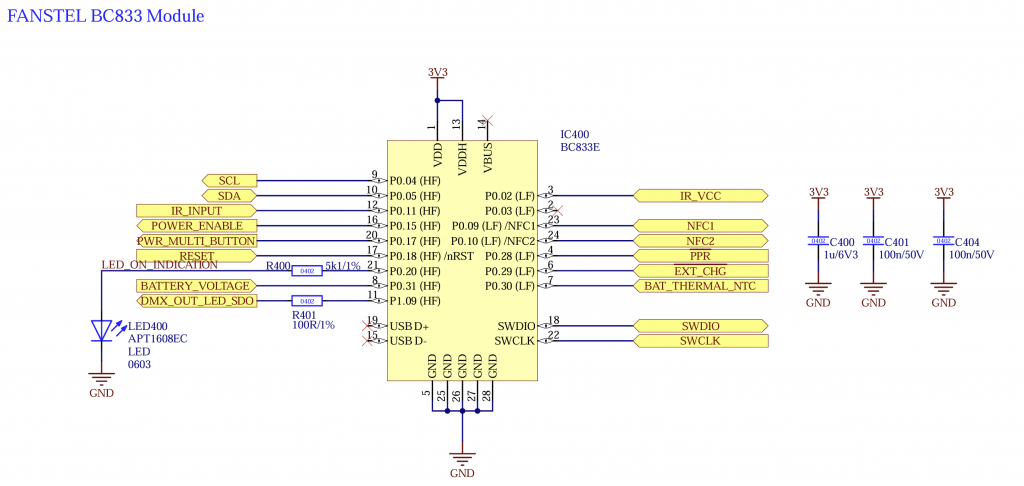
Please do not change the components and values. Ensure a stable +3.3V_Mesh supply with a minimum current delivery of 20 mA.
Please ensure that the capacitors are connected as close as possible to the controller.
| Pin | Description | Mandatory | Function | Use | Wiring |
| P0.04 | SCL | No | I2C Clock for for peripherals like motion and battery controller | Pull Up (4k7) | |
| P0.05 | SDA | No | I2C Data for for peripherals like motion and battery controller | Pull Up (4k7) | |
| P0.11 | IR_INPUT | No | IR Sensor Input for IR Remote | ||
| P0.15 | POWER_ENABLE | Yes | Turn on and off power from components needed during normal operation like LED Driver, additional controller, Motor driver, etc..Needed to make sure the current consumption while sleeping is minimal | Pull Down (100k) | |
| P0.17 | PWR_MULTI_BUTTON | Yes | Turn fixture on/off and unlink | ||
| P0.18 | RESET | Yes | Programming SWD | – | – |
| P0.20 | STATUS_LED | No | Signal Status LED | – | – |
| P0.31 | STATUS | No | UART RX for receiving additional information like battery state, etc.. You can find additional information under STATUS Interface | – | – |
| P1.09 | DMX/LEDSDI | Yes | DMX Stream / Different control protocoll depending on configuration | – | – |
| P0.02 | IR_VCC | No | Switchable supply voltage for IR Sensor (Needed for IR Remote) | – | – |
| P0.09 | NFC1 | No | NFC Antenna | – | – |
| P0.10 | NFC2 | No | NFC Antenna | – | – |
| P0.29 | CHG | No | Battery Management: Charging indication Input | Low: Charging High: No charging | |
| P0.28 | PPR | No | Battery Management: Power Presence | Low: Power available High: No power –> battery powered | – |
| P0.30 | BAT_NTC | No | Battery Management: Battery NTC | Connect NTC 10K using 10K resistor divider | – |
| SWDIO | SWDIO | Yes | SWD Programming Data | – | – |
| SWCLK | SWCLK | Yes | SWD Programming Clock | – | – |
The following components should be used:
- Fanstel BC833E or BC833M