




Ebyte E73-2G4M08S1
The contact person at Chengdu Ebyte Electronic Technology Co., Ltd is:
Serena Sun (Sales Manager & Technical Support Engineer)
Web: www.cdebyte.com
Email: sales01@ebyte.com / sunxiaomin@cdebyte.com
The following circuit shows an example Vision Core implementation using the Ebyte E73-2G4M08S1C / E73-2G4M08S1CX module. The physical module pad, nRF52840 GPIO, and Vision Core function are listed in the tables below.
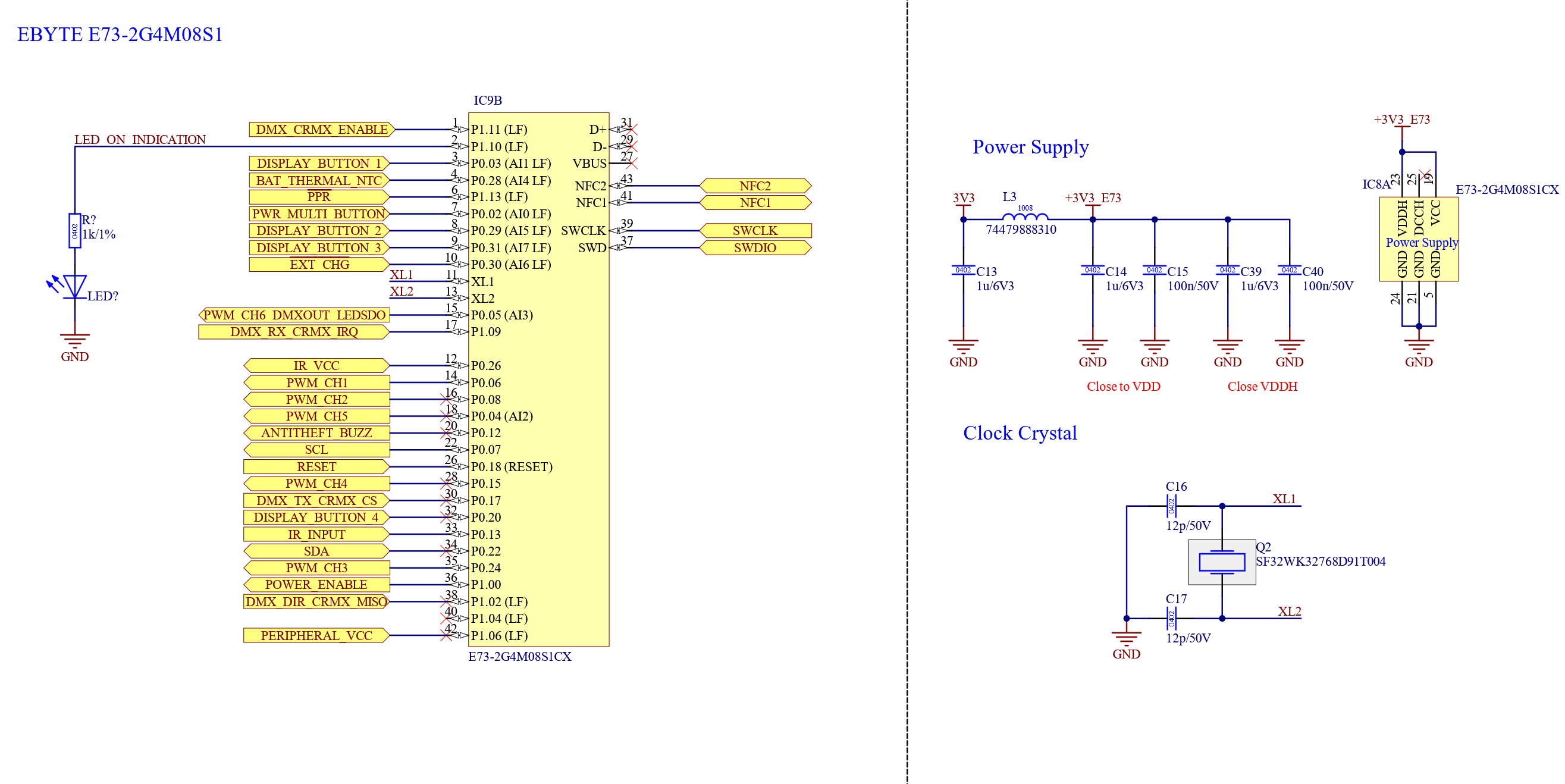
Please do not change the components or values shown in the reference circuit. Provide a stable +3.3 V supply capable of delivering at least 20 mA. Place the decoupling capacitors close to the module supply pins and provide a low-impedance grounding path.
GPIO speed classification: Pins marked LF are used only for buttons, indicators, enables, or other slow signals. The approximately 10 kHz value associated with the nRF52840 low-frequency GPIO recommendation is an RF-interference guideline, not a hard digital switching limit. Fast signal edges contain high-frequency components, so timing-critical signals are assigned to unrestricted GPIOs.
Analog assignments: BAT_THERMAL_NTC uses AIN4 on P0.28. Other AIN-capable pins assigned to buttons or charging inputs are used as slow digital inputs. P0.04/AIN2 and P0.05/AIN3 are used as unrestricted digital outputs and do not use the ADC function.
Vision Core signal assignments
| Module pad | GPIO | Description | Mandatory | Function and use | Pin note |
| 1 | P1.11 | DMX_CRMX_ENABLE | No | Enables or disables the DMX/CRMX interface to reduce power consumption. | LF; static output |
| 2 | P1.10 | LED_ON_INDICATION | No | Status/On indication LED output. | LF; low-frequency output |
| 3 | P0.03 / AIN1 | DISPLAY_BUTTON1 | No | Display button 1 input. | LF; slow digital input |
| 4 | P0.28 / AIN4 | BAT_THERMAL_NTC | No | Battery-management NTC analog input. Connect the NTC using the resistor divider selected for the firmware configuration. | AIN4; analog input |
| 6 | P1.13 | PPR | No | Battery-management power-presence input. Low: external power available. High: battery powered. | LF; slow digital input |
| 7 | P0.02 / AIN0 | PWR_MULTI_BUTTON | No | Button: power on/off and unlink. Switch: power on/off. | LF; slow digital input |
| 8 | P0.29 / AIN5 | DISPLAY_BUTTON2 | No | Display button 2 input. | LF; slow digital input |
| 9 | P0.31 / AIN7 | DISPLAY_BUTTON3 | No | Display button 3 input. | LF; slow digital input |
| 10 | P0.30 / AIN6 | EXT_CHG | No | External charger indication input when battery functions are used without a supported charger controller. Low: charging. High: not charging. | LF; slow digital input |
| 12 | P0.26 | IR_VCC | No | Switchable supply output for an IR receiver. | Static output |
| 14 | P0.06 | PWM_CH1 | No | PWM output channel 1. | Unrestricted GPIO |
| 15 | P0.05 / AIN3 | PWM_CH6_DMXOUT_LEDSDO | No | Shared output for PWM channel 6, DMX output, or serial LED data (WS2812/I²S). Only one function may be active at a time; deinitialize the active peripheral before changing modes. | Unrestricted GPIO; shared function |
| 16 | P0.08 | PWM_CH2 | No | PWM output channel 2. | Unrestricted GPIO |
| 17 | P1.09 | DMX_RX_CRMX_IRQ | No | DMX/RDM receive input or CRMX interrupt input. | Unrestricted GPIO |
| 18 | P0.04 / AIN2 | PWM_CH5 | No | PWM output channel 5. | Unrestricted GPIO |
| 20 | P0.12 | ANTITHEFT_BUZZ | No | Antitheft buzzer output. | Unrestricted GPIO |
| 22 | P0.07 | SCL | No | I²C clock for peripherals such as motion sensors, battery controllers, battery gauges, and displays. | 4.7 kΩ pull-up |
| 28 | P0.15 | PWM_CH4 | No | PWM output channel 4. | Unrestricted GPIO |
| 30 | P0.17 | DMX_TX_CRMX_CS | No | DMX/RDM transmit output or CRMX chip-select output. | Unrestricted GPIO |
| 32 | P0.20 | DISPLAY_BUTTON4 | No | Display button 4 input. | Digital input |
| 33 | P0.13 | IR_INPUT | No | IR receiver signal input, for example from an IRM-H6XXT/TR2 or Vishay TSOP2436. | Unrestricted GPIO |
| 34 | P0.22 | SDA | No | I²C data for peripherals such as motion sensors, battery controllers, battery gauges, and displays. | 4.7 kΩ pull-up |
| 35 | P0.24 | PWM_CH3 | No | PWM output channel 3. | Unrestricted GPIO |
| 36 | P1.00 | POWER_ENABLE | No | Enables components required during normal operation, such as LED or motor drivers, while allowing low-power shutdown. | Static output; 100 kΩ pull-down |
| 38 | P1.02 | DMX_DIR_CRMX_MISO | No | RS-485 direction output for DMX/RDM or CRMX MISO input. | LF; static output or slow input |
| 40 | P1.04 | SPARE | No | Reserved spare GPIO. Use only for a future low-frequency or static signal. | LF; do not assign a timing-critical signal |
| 42 | P1.06 | PERIPHERAL_VCC | No | Controls a switched peripheral supply, for example the supply used by optional sensors or an NTC divider. | LF; static output |
PWM outputs
This E73 Vision Core implementation exposes six PWM channels. PWM6 shares its physical pin with DMXOUT and LED_SDO.
| Channel | GPIO | Module pad | Note |
| PWM1 | P0.06 | 14 | Dedicated PWM output |
| PWM2 | P0.08 | 16 | Dedicated PWM output |
| PWM3 | P0.24 | 35 | Dedicated PWM output |
| PWM4 | P0.15 | 28 | Dedicated PWM output |
| PWM5 | P0.04 / AIN2 | 18 | Digital PWM function; ADC function unused |
| PWM6 / DMXOUT / LED_SDO | P0.05 / AIN3 | 15 | Mutually exclusive output modes |
Power, programming, and reserved module pads
| Module pad | Pin | Mandatory | Use |
| 5 | GND | Yes | Ground; connect to the ground plane. |
| 11 | P0.00 / XL1 | Yes | 32.768 kHz crystal connection. Do not use as GPIO. |
| 13 | P0.01 / XL2 | Yes | 32.768 kHz crystal connection. Do not use as GPIO. |
| 19 | VDD | Yes | Module supply; connect exactly as shown in the reference circuit. |
| 21 | GND | Yes | Ground; connect to the ground plane. |
| 23 | VDDH | Yes | Module supply connection; follow the reference circuit and Ebyte datasheet. |
| 24 | GND | Yes | Ground; connect to the ground plane. |
| 25 | DCCH | Yes | DC/DC supply connection; follow the reference circuit and Ebyte datasheet. |
| 26 | P0.18 / RESET | Yes | Hardware reset and programming interface. |
| 27 | VBUS | No | USB supply detection. Leave unconnected when USB is not used. |
| 29 | USB D− | No | USB data. Leave unconnected when USB is not used. |
| 31 | USB D+ | No | USB data. Leave unconnected when USB is not used. |
| 37 | SWDIO | Yes | SWD programming/debug data. |
| 39 | SWDCLK | Yes | SWD programming/debug clock. |
| 41 | P0.09 / NFC1 | No | NFC antenna connection. Reserve this pin when NFC may be used. |
| 43 | P0.10 / NFC2 | No | NFC antenna connection. Reserve this pin when NFC may be used. |
The following components should be used:
- Ebyte E73-2G4M08S1C or E73-2G4M08S1CX
- 32.768 kHz crystal “EPSON FC-135 32.7680KA-AC0” or “SF32WK32768D91T004”