




Simple Product Guide
Simple Product Workflow: Direct LED Output and Button/Touch
This page is a short route through the Core documentation for simple products where the Core module directly controls the LEDs and uses one local button or touch input.
Simple hardware examples
The following schematics show typical simple hardware variants using the Abluetech PTR9813/PTR9813+ module. The same signal names are used for other supported Core modules, but the physical GPIO pins can be different. Always use the pin table and reference schematic for the exact module used on the PCB.
Example 1: WS2812 LEDs without battery management
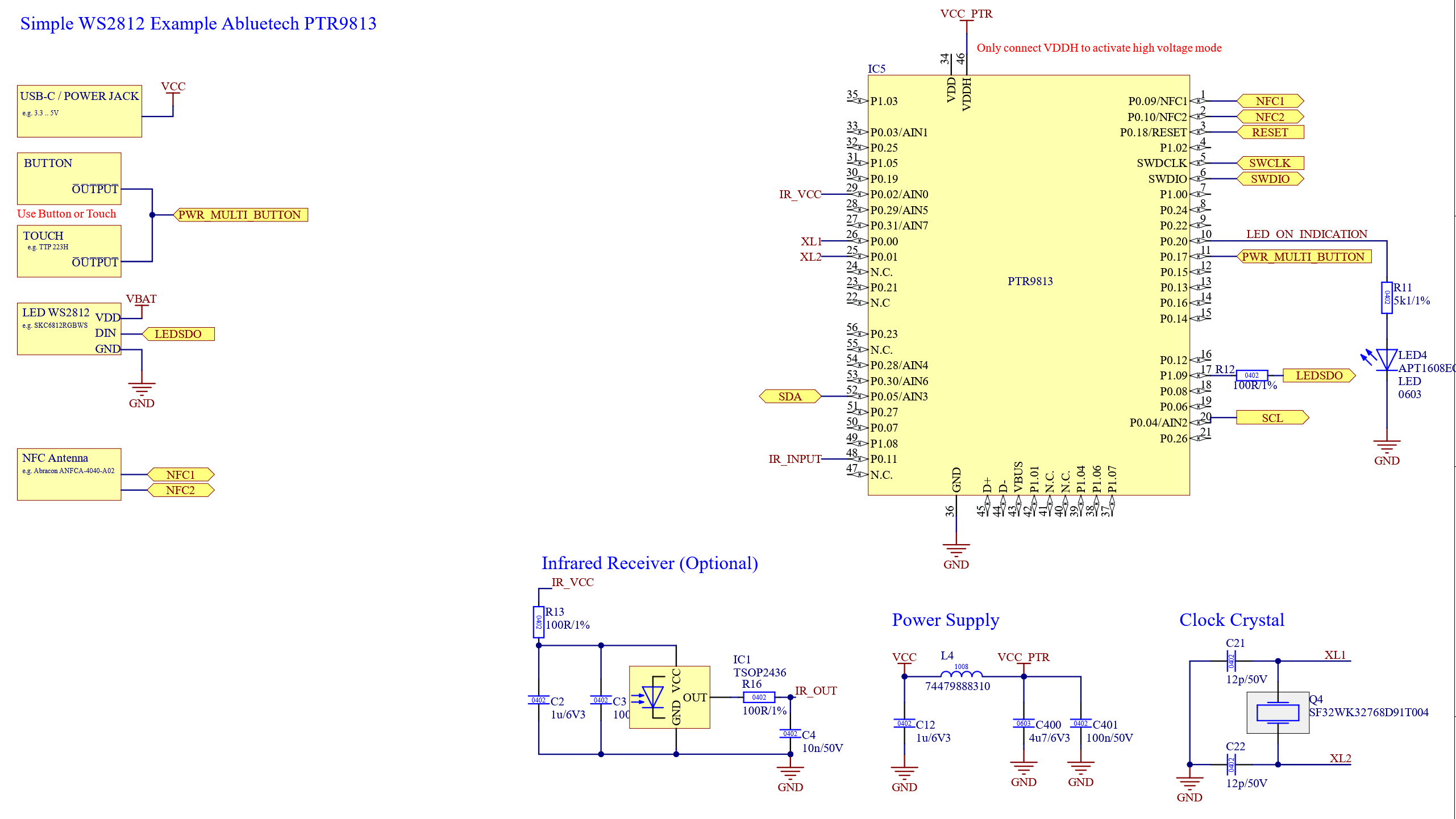
This is the simplest direct LED implementation. The product is powered externally, the Core module controls the WS2812 chain with one data output, and the local input is connected to PWR_MULTI_BUTTON.
Example 2: WS2812 LEDs with single-cell battery
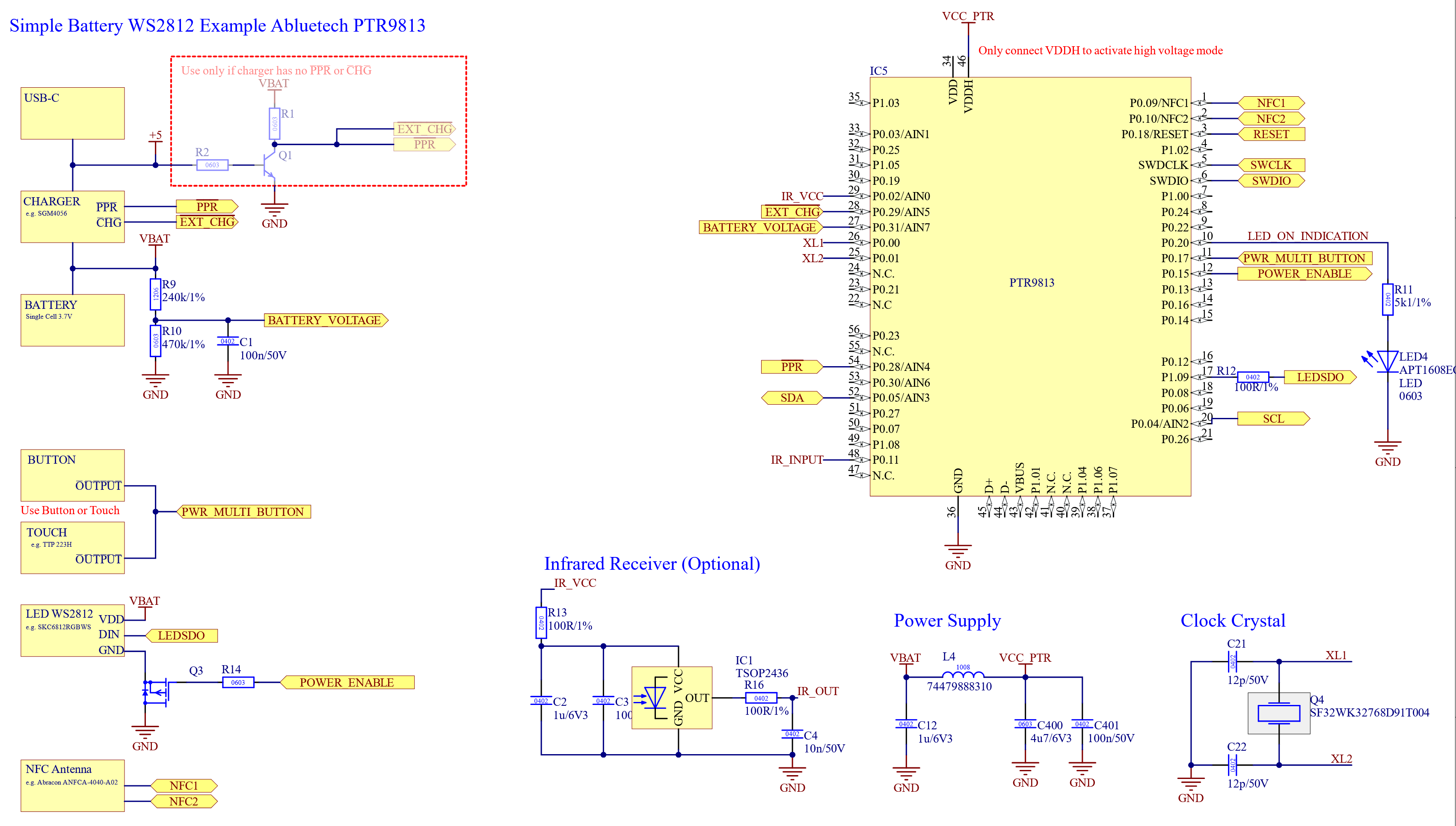
This variant uses the same WS2812 output concept, but adds a single-cell 3.7V battery, a simple charger, and basic battery voltage measurement. If no dedicated battery gauge is used, BATTERY_VOLTAGE can be used for a rough battery state measurement.
Example 3: PWM LEDs with single-cell battery
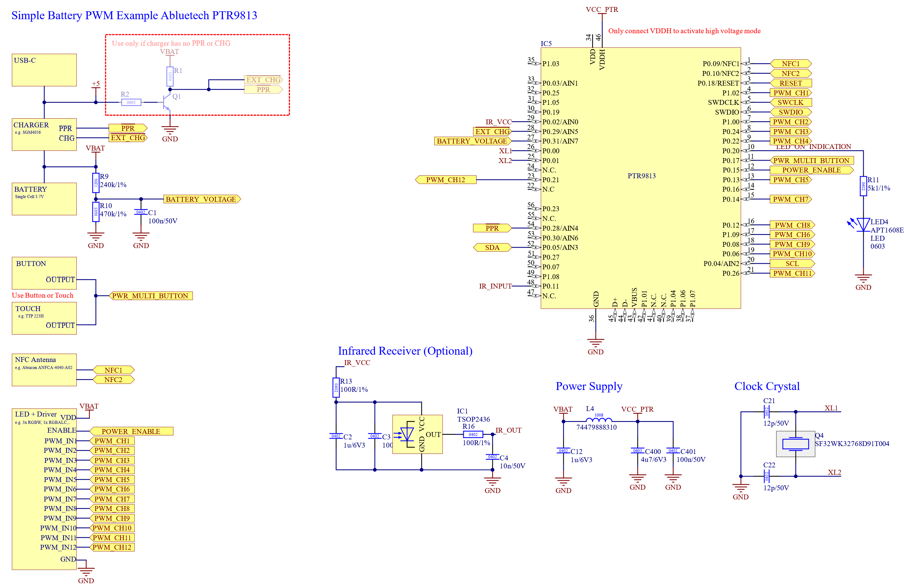
This variant uses the same battery, charger, voltage measurement, and button/touch concept, but the Core module controls individual PWM channels instead of a WS2812 data chain.
Important for the battery variants:
- The Core supply must stay available while the battery is connected. Do not switch off the Core supply together with the LED power stage.
- BATTERY_VOLTAGE must not be connected directly to the battery. Use a resistor divider: Battery + -> 240k -> BATTERY_VOLTAGE -> 470k -> GND, with 100nF from BATTERY_VOLTAGE to GND.
- Configure the battery charger and voltage measurement only when the product actually contains this hardware.
1. Create the PCB and schematic
Important for this use case:
- Choose one of the supported Core modules from the Radio Module section. Purchase it from the module manufacturer or a suitable electronics supplier and integrate it into your PCB using the documentation for that exact module.
- Decide whether the product uses WS2812 LEDs or PWM LED channels. Connect the LED outputs to the matching signals shown in the selected module's pin table.
- Connect the local button or touch controller output to PWR_MULTI_BUTTON. This signal name is the same for every supported module, although its physical GPIO is module-specific.
- If the product uses the simple battery variant, add the charger, the always-available Core supply, and the BATTERY_VOLTAGE resistor divider shown above.
- Keep the SWD programming connection accessible so the module can be flashed after PCB assembly.
Follow:
- Hardware → Overview
- Hardware → Radio Module → select the matching module:
- Hardware → Peripherals → Turn On/Off/Unlink Button
- Hardware → Power Supply
- Interfaces → WS2812
- Interfaces → PWM
2. Create a company account
Important for this use case:
- Create the user account in the Vision Control App and use the same credentials on the Vision server.
- The company account is required before you can create the fixture and manage its Core and Creative configurations.
- The company request must be approved. Submit it early so approval does not block the following steps.
Follow: Release & Production → Create Company.
3. Create the fixture and Core Configuration
Important for this use case:
- Create the fixture entry before creating its Core Configuration. The fixture entry provides the product identity to which the configurations belong.
- Select the exact Core module installed on the PCB and choose the correct output type: WS2812 or PWM.
- Enter the LED power draw values so they match the LEDs used in the product.
- Configure PWR_MULTI_BUTTON according to the intended button or touch behavior.
- If the product uses the simple battery variant, enable the matching charger option and basic battery voltage measurement. Leave unused optional hardware and interfaces disabled.
Follow: Release & Production → Create Fixture.
4. Create the Creative Configuration
Important for this use case:
- Configure only the color component because the product has no other controllable components.
- For WS2812 products, set the number and position of the pixels to match the physical LED chain.
- For PWM products, define the LED component, color channels, channel order, and calibration values according to the actual fixture hardware.
- Select the color order used by the installed LEDs. An incorrect color order or channel order causes the wrong colors to be displayed even when the configuration is otherwise correct.
- Write the Creative Configuration to the fixture and test every pixel or PWM channel in Creative Control before uploading the configuration to the fixture entry.
Follow:
5. Create the flash file
Important for this use case:
- Select the exact Core module and the correct fixture when generating the flash file.
- The production flash file can contain both the Core and Creative configurations. This reduces the number of manual app steps required for every unit in production.
- The combined file is optional for development samples. You can flash the standard bootloader and write both configurations through the Vision Control App instead.
Follow: Release & Production → Prepare Modules → VISION Bootloader Flash File Generation.
6. Connect with the app, update, and set the serial number
Important for this use case:
- Connect to the assembled fixture with the Vision Control App and install any required firmware update.
- If the production flash file did not contain the final configurations, update the Core and Creative configurations through the app.
- Assign a unique serial number to every produced fixture. Scan again afterwards and confirm that the correct fixture identity and serial number are shown.
- Verify every WS2812 pixel or PWM channel, the displayed colors, the local button/touch function, and the battery display if the product uses the simple battery variant.
Follow: