Summary
1. Understand Vision
What to implement
- Treat the Vision Controller as the radio and app interface between the Vision Control App and the fixture main controller.
- Use SPI between the Vision Controller and the fixture main controller.
- Understand the app workflow first: search for fixtures, connect to a fixture, create a network, link fixtures, and control selected groups or fixtures.
Important rules
- Vision was previously called iQ or iQ.Mesh. Older documentation, screenshots, or code packages may still use the old name.
- Vision is based on standard DMX and RDM concepts.
- If the fixture already supports wired DMX and wired RDM, reuse the same DMX handling and the same RDM implementation as much as possible.
- Do not create a second independent RDM library only because the data comes through Vision.
- The app uses fixture RDM information for discovery, status, warnings, errors, DMX settings, firmware versions, and customer-facing control.
- Vision Control Behavior 0 is DMX Control and shall behave like wired DMX.
- Vision Control Behavior 255 is App Control and uses fixed app-specific defaults for the current frame.
Test immediately
- Before writing new firmware, confirm which existing wired DMX and RDM code can be reused.
- Check that the team understands the two normal control behaviors: DMX Control and App Control.
- Check that nobody plans to add a duplicated RDM stack unless the existing architecture really requires it.
Common mistakes
- Assuming Vision uses a different RDM protocol.
- Introduction (included below)
- Vision Control App Overview (included below)
- Information to Prepare Before Implementation (included below)
- Software Overview (included below)
- Example Project Overview (reference link) - Helpful to understand the full example project before starting.
- Step by Step (reference link) - Reference only; this guide contains the updated implementation flow.
- FAQ (reference link) - Use for additional questions, not as the main implementation path.
Introduction
1_Introduction.htmlDear Developer,
welcome to this comprehensive guide designed to help you understand and integrate our platform into your software. We have prepared detailed documentation to ensure a smooth implementation process. Although the information is extensive and detailed, please don’t feel overwhelmed. We included a lot of details to prevent any misunderstandings. We recommend going through the documentation step by step. Should you have any questions or require further clarification, do not hesitate to contact us via email or reach out to your local representative at Vision Control Solutions GmbH.
Mail: info@vision-cs.de
We prepared a step for step guide for the implementation. Please follow the steps carefully.
Legacy naming: Earlier versions of this documentation and some older source files used the name iQ or iQ.Mesh. This has been renamed to Vision. In customer-facing documentation, use Vision terminology. Current libraries and customer-facing documentation use Vision naming. Older packages or screenshots may still contain iQMesh/iqMesh; treat those as the previous names for the same Vision components.
Should you encounter any insufficient documentation, please do not hesitate to reach out. We are more than willing to assist you, ensuring that you have the optimal experience during the implementation process.
External Module
The External Module serves as an interface enabling communication with the Vision Control App. It connects to the fixture's main controller via SPI. Functionally, it is comparable to a WDMX/CRMX module, but with a tighter and more direct integration into the fixture's internal interface.
Communication is primarily based on RDM. The concept is that you design and manufacture your own hardware, select a supported Vision IC (listed on the Hardware -> Modules page), flash the provided firmware, and finally license the module for operation.
Vision is based on standard DMX and RDM concepts. If your fixture already supports wired DMX and RDM, reuse the same DMX handling and the same RDM implementation as much as possible. Vision does not require a separate second RDM stack. Only App Control uses defined fixed DMX behavior so the app can control all fixtures of the same type consistently.
Core Module
The Core Module is a standalone fixture controller with native support for the Vision Control App. It can be customized to match the fixture's hardware requirements, such as direct LED control and other peripheral functions.
It is designed to enable complete product implementations based solely on a Vision IC. The procedure is identical to the External Module: you design your own hardware, select a supported Vision IC, flash the provided firmware, and license the module for use in production.
Naming Scheme
Protocol Name: Vision Control
Vision Control App Overview
2_Vision_Control_App_Overview.htmlUnderstand the Vision Control App First
Before starting the firmware implementation, it is helpful to understand how the Vision Control App is used by the customer. The app is not only a test tool as it seems if you activate testmode. It is the user interface for finding fixtures, creating a wireless network, connecting to fixtures, reading status information, and controlling fixture parameters.
General app information, download links, feature descriptions, and tutorial videos are available on the Vision Control website:
https://visioncontrolapp.com/
Additional product and workflow information is also shared through the WeChat channel:
VCS Vision Control Solutions GmbH
The detailed app manual contains many screenshots and step-by-step explanations:
https://visioncontrolapp.com/manual/
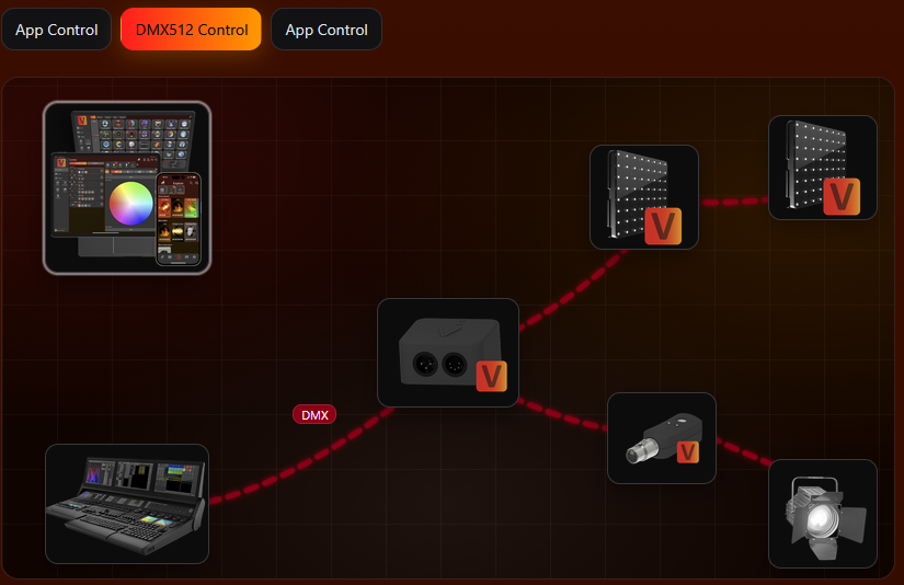
Two Control Scenarios
Vision supports two main control scenarios. They are important for the implementation because they explain why DMX Control and App Control must behave differently.
Vision DMX Control
In DMX Control, the fixture behaves like it does with wired DMX. Vision transports the DMX data wirelessly, but the fixture should use the same DMX personality, DMX start address, and DMX/RDM logic as the wired implementation.
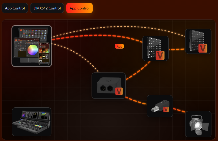
Vision App Control
In App Control, the app controls the fixture directly through the Vision network. The app needs predictable parameter positions for fixtures of the same type, so the current Vision frame uses the App Control Configuration. This does not replace the saved RDM settings of the fixture.
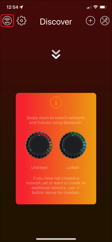
Basic App Workflow
- Install and prepare the app. Install Vision Control on iOS, Android, or Windows. On first start, grant the required permissions, especially Bluetooth access.
- Search for fixtures. Open the Discover page. On mobile, swipe down to scan. On desktop, use the refresh button. Fixtures must be powered on, within radio range, and configured to use Vision as input source.
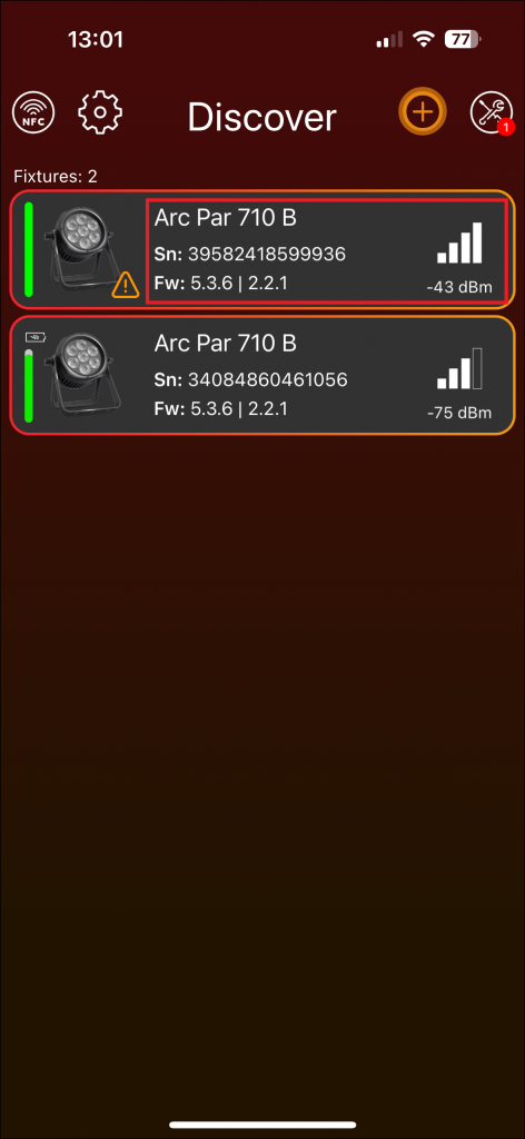
- Connect to a fixture. Click the fixture frame to open the fixture page. The fixture page shows important status information such as input source, DMX address, DMX mode, signal strength, firmware versions, warnings, and errors.
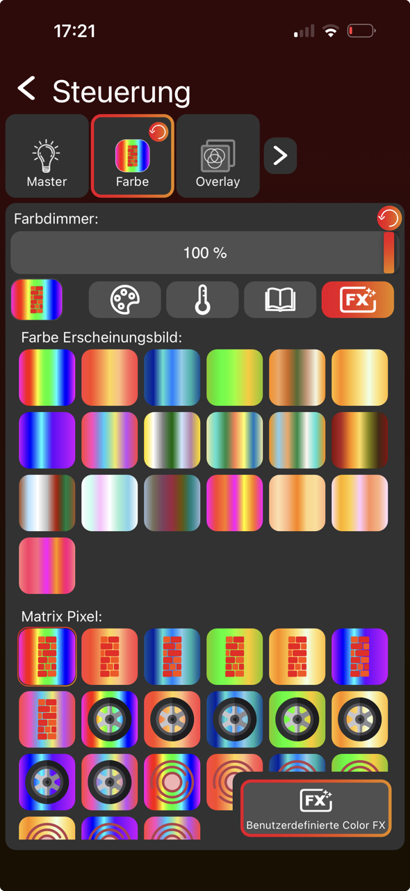
- Control fixtures. Select groups or fixtures on the Lights page, then adjust values on the Control page. Only supported fixture components are shown, for example dimmer, color, pan, tilt, zoom, projection, or special functions.
- Use status and test functions. Use identify, reset, test modes, warning/error information, firmware updates, and RDM-related tools to verify the fixture during development.
Example Screens From the Manual
The following screenshots show the basic app areas that are most important for implementation: searching for fixtures, reading fixture information, and controlling fixture parameters. Use the full manual for the complete explanation of every app page and button.
Why This Matters for Implementation
- The fixture must be discoverable before the customer can connect or link it.
- The app reads fixture information through RDM, so RDM data must be correct and understandable. RDM Communication must be always available.
- The input source must clearly show whether the fixture is controlled by Vision, DMX, or another source.
- DMX Control should reuse the same behavior as wired DMX.
- App Control must use the App Control Configuration so the app can show and control the correct fixture parameters.
- Warnings, errors, firmware versions, and test functions should be implemented early because they make development and customer support much easier.
Information to Prepare Before Implementation
5_Reseller_Notes.htmlThe following page summarizes the key topics to consider when purchasing a Vision-compatible fixture from a manufacturer under your own company branding.
RDM (Remote Device Management)
Vision is based pureley on RDM and therefore requires an RDM compliant fixture. So if you are not an RDM Manufacturer, the first step is to register your company.
RDM Manufacturer ID & RDM Device Model ID
Verify that the RDM Manufacturer ID and RDM Device Model ID of your fixture are correct in both cases: In the Vision Control app and via RDM on the console. Keep track of all assigned Device Model IDs, as duplicate IDs can lead to system conflicts and corruption.
Vision Specification
Specify your Vision featureset with the manufacturer. You will find an example Fixture Specification for download here:
Check Fixture & Software
For each fixture firmware version, ensure that the basic Vision Control features are functioning correctly by passing the verification process. Here is the documentation: #source-77_Implementation_Verification_Tool
Please make sure to test the fixtures on your side, or alternatively send some units to our headquarters so we can verify them. Without this verification, we cannot guarantee that all features will work correctly, and we may not be able to provide reliable solutions for future issues.
Server & Product Management
Request control and access to your branded fixtures library in the Vision Webservice from your manufacturer. This is required so you can manage the products yourself. Therefore, the manufacturer will need your Vision Company ID.
Software Overview
23_Software_Overview.htmlThis chapter offers guidance on writing the essential software that enables your controller to communicate with the Vision Controller and the Vision Control App.
To get your implementation running there are 6 topics to accomplish.
- System
- SPI Interface
- Vision RDM
- Vision DMX
- Vision DFU
- Display
Our example project covers all these topics. For each one, you can check out our sample project to get a better understanding.
Definitions
There are several important definitions:
Main Controller: The controller on the fixture side.
Vision Controller: The Bluetooth/mesh controller (NRF52840, etc.) with the Vision firmware.
Older documents, screenshots, API names, and file names may still use iQ or iQ.Mesh. In the current documentation, this is called Vision or Vision Protocol. Current libraries use Vision header and API names. Older code packages or screenshots may still show iQMesh/iqMesh; treat those as legacy names for the same Vision library.
2. Hardware Setup
Goal: Integrate the Vision Controller hardware so the firmware can communicate reliably and the radio performance is usable.
What to implement
- Select a supported Vision IC or module and use the corresponding pinout page.
- Connect SPI, chip select, IRQ, reset, programming pins, and mandatory power pins according to the selected module.
- Implement the required FIXTURE_IS_ON and wakeup behavior according to the power concept of the fixture.
- Design the power supply so the Vision Controller remains stable during normal operation, sleep, wakeup, and update cases.
- Place the antenna according to the antenna design rules and keep it away from metal or noisy electronics where possible.
- Flash the provided Vision Controller firmware for the selected hardware module.
Important rules
- The Vision Controller power supply must be stable at 3.3 V and should not be noisy.
- The 32.768 kHz crystal accuracy is important for reliable Bluetooth connections.
- FIXTURE_IS_ON must reflect whether the fixture is actually in normal operation.
- Optional features such as NFC, IR, motion, battery runtime, or antitheft may require additional hardware.
- For battery fixtures, the wakeup and low-power behavior must be designed before firmware testing.
Test immediately
- Measure the 3.3 V supply during startup, normal operation, radio activity, and firmware update.
- Check that the Vision Controller can be flashed and starts with the expected firmware.
- Check that FIXTURE_IS_ON and MAIN_WAKEUP behave correctly during normal operation and wakeup.
- Do a first radio scan and confirm the fixture is visible with reasonable signal strength.
- For final hardware validation, use the radio signal measurement procedure.
Common mistakes
- Testing firmware while the power supply or wakeup pins are still unstable.
- Placing the antenna in a position that makes the fixture pass on the bench but fail in a real housing.
- Forgetting optional feature hardware until after the PCB is finished.
- Requirements (included below)
- Features (included below)
- Hardware Modules Overview (included below)
- Hardware Module - Fanstel BT840 (reference link) - Use this pinout only when this module is selected.
- Hardware Module - Wuerth Proteus Ophelia III (reference link) - Use this pinout only when this module is selected.
- Hardware Module - Fanstel BC833 (reference link) - Use this pinout only when this module is selected.
- Hardware Module - Abluetech PTR9818 (reference link) - Use this pinout only when this module is selected.
- Hardware Module - Abluetech PTR9813 / PTR9813+ (reference link) - Use this pinout only when this module is selected.
- Hardware Module - AT833 (reference link) - Use this pinout only when this module is selected.
- Hardware Module - Other Modules (reference link) - Use only if your hardware is not covered by the listed module pages.
- Peripherals (included below)
- Power Supply (included below)
- Antenna Design (included below)
- Vision Firmware (included below)
- Example Project Hardware (reference link) - Helpful to understand the example hardware.
- Custom Hardware Design (reference link) - Custom helper.
- Limitations (reference link) - Use as a final hardware sanity check.
Requirements
7_Requirements.htmlBefore starting development, it’s crucial to understand the project’s requirements. These specifications outline what the software or system must fulfill to operate properly. Please review the serial number, RDM (Remote Device Management), DMX (Digital Multiplex), and DFU (Device Firmware Update) requirements below.
Serial number (S/N)
The fixture must have a unique serial number, which should be visible on the fixture. This serial number is used to identify the fixture in the app. The serial number can be any number smaller than 72057594040000000. Ideally, the serial number has two parts. The fixed front part shows the fixture type and hardware revisions, while the incremental back part can interpret it as a numerical value by the users.
Example serial number:
1000100100
Front Part: Is used to derive fixture type and hardware revisions.
Back Part: Is incremental number so users can recognize it is fixture 100.
Firmware Versioning
We require a semantic versioning scheme.
[Major,Minor,Patch,Release] (Semantic Versioning) Every part is 8 bit and we have added a Release part to indicate if it is an release version or not. Release have to be 255 in order to be publicly available via the server. Otherwise the server will reject your software because it is only an developer version.
Major: Incompatible change. There is a change which changes the behavior of the fixture
Minor: There is a new feature in the firmware
Patch: There is a bug fix in the firmware
Release: 0-254: Internal Firmware for testing ; 255: Public available firmware
RDM (Remote Device Management)
A working RDM interface is essential for the complete implementation. Here’s a link explaining how RDM operates. Please take a look:
- RDM Manufacturer ID
A 16-bit (2-byte) value assigned by ESTA to each manufacturer.
This ensures every manufacturer can create globally unique identifiers.
Think of it like the "Organizationally Unique Identifier" (OUI) in Ethernet MAC addresses. Examples:
VCS Vision Control Solutions GmbH : 0x0969 - RDM UID A 48-bit (6-byte) unique identifier for every RDM-capable device.
Format: [16-bit ManufacturerID] + [32-bit DeviceID]
The DeviceID is assigned by the manufacturer, unique per device. Could be sequential, random, or based on a serial number. Example:
Manufacturer ID = 0x6574 (ETC)
DeviceID = 0x12345678
RDM UID = 0x6574:12345678 So this UID uniquely identifies one physical RDM device in the world. - RDM DeviceModelID A 16-bit value that identifies the model of a device, within a manufacturer's range.
Assigned by the manufacturer, not by ESTA.
Same manufacturer can have multiple models, each with its own DeviceModelID. Example:
Vision External Module: DeviceModelID = 0x0001
Vision Core Module: DeviceModelID = 0x0002 Both still under ManufacturerID 0x0969, but distinguished via DeviceModelID.
- Standard RDM Commands like DeviceInfo should be supported. A detailed list is provided in Software documentation.
- Custom RDM Commands. We need you to support some simple custom PIDs to get/set all required information.
DMX (Digital Multiplex)
We have some specific requirements to control your fixtures properly. The refresh rate over our protocol is fixed set to 20ms. Components which can be implemented have some requirements too:
- LED Color Control
- Supports up to 6 Colors
- Supports up to 100 pixel individually
- 8 bit or 16 bit linear
- Reaction speed should be instant (Snap). For smoothing the dimming use our code template.
- LED White Control
- Supports up to 100 pixel individually
- 8 bit or 16 bit linear
- Reaction speed should be instant (Snap). For smoothing the dimming use our code template.
DFU (Device Firmware Update)
For software updates a bootloader on your controller is necessary. In the example you can find a simple bootloader. We support dual and single bank bootloader.
Features
9_Features.htmlThe implementation consists of mandatory features, which are always required, and optional features, which you can add depending on your product design. Before starting with the hardware it is important to know what to additionally integrate. Below is an overview:
Mandatory Features
- App Control - Enables configuration and control of the fixture through the Vision App. This is the primary interface for end users.
- DMX Control over Vision Protocol – Provides standard DMX512 control for integration with lighting consoles. This ensures compatibility with professional lighting setups.
- Firmware Update – Ensures the device can be updated via the app using DFU (Device Firmware Update) packages. Critical for bug fixes, feature upgrades, and long-term product support.
- RDM Configuration – Allows remote configuration via RDM (Remote Device Management) when the fixture is used with either the Vision Control App or Vision Control Gateway
Optional Features
- NFC Connect / NFC DMX Patching - Allows quick configuration and pairing of the fixture using NFC.
Requirement: NFC antenna integrated into the hardware. - IR Remote Control - Enables remote control of basic functions using an IR remote
Requirement: IR sensor installed in the fixture and connected to Vision Controller - IR Remote Wake-Up (Battery driven Fixtures) – Enables Wake Up or turning on the Fixture using an IR remote
Requirement: Suitable for battery driven fixtures. Vision Controller must be always connected directly to the battery. IR sensor installed in the fixture and connected to Vision Controller. - NFC Wake-Up (Battery driven Fixtures) – Enables Wake Up or turning on the Fixture using NFC
Requirement: Suitable for battery driven fixtures. Vision Controller must be always connected directly to the battery. NFC antenna integrated into the hardware. - NFC DMX Patching without A/C Grid Power – Allows quick configuration using NFC without the fixture being powered
Requirement: Small battery for configuration necessary. Vision Controller must be always connected directly to this battery. Vision Control must be able to wake up the main controller through WakeUp Pin for communication. - App Control Scene Retention Across Power Cycles - Ensures the fixture automatically resumes the last active scene after being powered off and on again. This allows seamless operation without user interaction after power loss or intentional shutdown.
Requirement: A small battery is required, and the Vision Controller must remain permanently powered by this battery. - Universal Time Support - Provides a stable internal time source for timestamping, logging, and scheduled actions (e.g., timed scenes or automated behaviors).
Requirement: A small battery is required to maintain timekeeping when the main power is off. - Sleep Mode - Reduces power consumption when the fixture is not in active use. Useful for battery-powered products.
- Battery Runtime Selection - Lets the user adjust brightness/output levels to extend operating time when running on battery.
- Emergency Mode - Ensures the fixture provides basic light output in case of power failure, following emergency lighting standards.
- Anti-Theft Mode - Triggers alarms or signals if unauthorized motion is detected.
Requirement: Motion sensor integrated into the hardware. - Shipping Mode - Disables unnecessary functions during transport to save power and avoid accidental activation.
Hardware Modules Overview
11_Hardware_Modules_Overview.htmlThere is support for two different ICs:
- nRF52833 (https://www.nordicsemi.com/products/nrf52833)
- nRF52840 (https://www.nordicsemi.com/products/nrf52840)
Out of the Box we support the following hardware modules:
- Fanstel BC833: https://www.fanstel.com/bc833
- BC833M: Integrated PCB Antenna + Integrated 32.768KHz crystal
- BC833E: External Antenna using u.FL + Integrated 32.768KHz crystal
- Fanstel BT840: https://www.fanstel.com/bt840
- BT840F: Integrated PCB Long Range Antenna
- BT840E: External Antenna using u.FL
- BT840: Integrated PCB Antenna
- Wuerth Ophelia III (https://www.we-online.com/de/components/products/OPHELIA-III)
- Integrated PCB Antenna or External Antenna depending on pcb
- Wuerth Proteus III (https://www.we-online.com/en/components/products/PROTEUS-III)
- Integrated PCB Antenna or External Antenna depending on pcb
- Abluetech PTR9818 (https://www.abluetech.com/BLE%2052%20Series/484.html)
- Integrated PCB Antenna
- Abluetech PTR9813
- PTR9813: Integrated PCB Antenna
- PTR9813+: External Antenna using u.FL
We will try to include these modules soon too. If you choose one of them, let us know. So we can provide you the necessary instruction faster:
- Ezurio BL654 PA
- Minew Semi nRF52840-MS88SF23
- Moko MK08
- Panasonic PAN1770
- RayTac MDBT50Q-U1MV2
- Ublox BMD-34
- Minew Semi nRF52840-MS88SF23
- Moko MK07
- Raytac MDBT50Q-512K
- NINA-B400-00B
Peripherals
19_Peripherals.htmlWe provide various peripherals to enhance functionality. All peripherals are optional, allowing you the flexibility to choose which features to implement in your product. If you are interested in integrating any of these peripherals, detailed documentation can be found below. Currently, we support NFC Antenna, Motion Controller, and IR Sensor. All omponents are wired to the Vision Controller.
NFC Antenna
The NFC antenna can be used to establish a fast connection with the fixture and to push or read some information. The NFC Antenna can be placed on the PCB itself or using an antenna connector. In the following is the schematic provided:
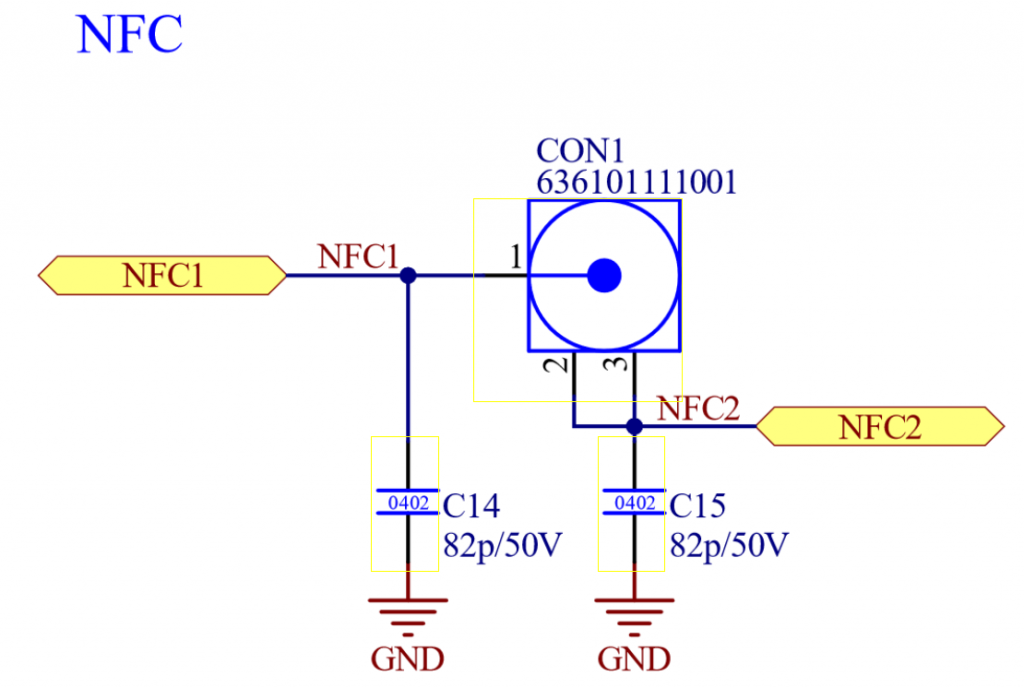
Used Part: „WR-UMRF PCB Receptacle SMT with 3 Pads, 50Ohm, DC~6GHz 636101111001“
For Antenna tuning please refer to the nordic documentation:
https://docs.nordicsemi.com/bundle/nwp_026/page/WP/nwp_026/nWP_026_intro.html
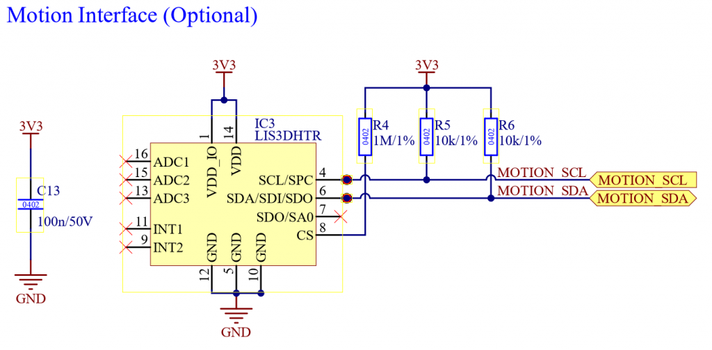
Motion Controller
The motion controller can be used for security features like anti theft mode. The Vision controller supports the „ST LIS3DH“ from STMicroelectronics and MSA311 from MEMSensing Microsystems. Further information can be found under https://www.st.com/en/mems-and-sensors/lis3dh.html and https://cdn-shop.adafruit.com/product-files/5309/MSA311-V1.1-ENG.pdf. Wire the Motion controller to the Vision ICs I^2C. In the following is the schematic provided:
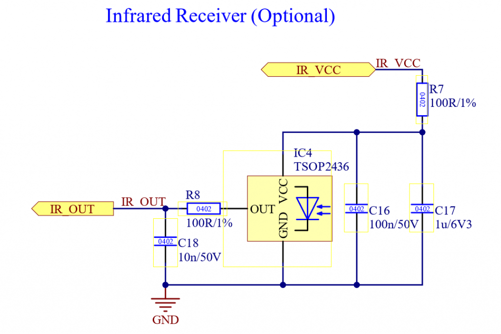
IR Sensor
The IR Sensor can be used for turning on, turning off and control the fixture in a simple manner. The Vision controller supports the following IR Receiver:
- IRM-H6XXT/TR2
- Vishay TSOP2436
In the following is the schematic provided:
Schematic for all peripherals (NFC Antenna, Motion Controller, and IR Sensor):
Power Supply
20_Power_Supply.htmlThe Power Supply for the Vision Controller has the following requirements:
- Voltage typical 3.3V (Max 3.6V, Min 1.7V)
- Maximum Current: 20mA
- Vision Controller Sleep current: 14uA
- Vision Controller typical operating current: 10mA
A block diagram of the schematic for the Vision Controller regarding power supply and state inputs may look like this if it is a battery supplied fixture:
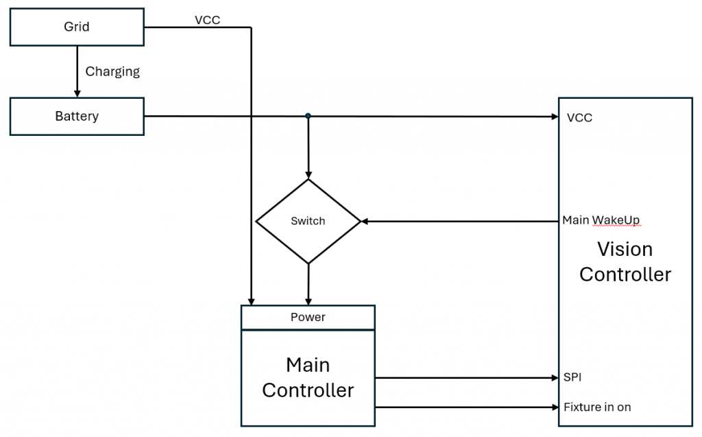
There a different ways how this can be done. Depending on your on the fixture and how good you support the features here is an overview on how you could implement it. The Schematics contains simple blocks to get you the idea.
| Fixture Type | Description | Support IR Wake Up | Support NFC Wake Up | Support Antitheft Stay On | Example Schematic |
| Grid powered (AC powered) fixture | This type of fixture does not have a battery inside. It just is powered by the grid. | NO | NO | NO | — |
| Grid powered fixture (AC powered) + Battery for configuration | This type of fixture does have a battery inside but just for the logic and not for powering for example the leds. It allows the fixture to be configured while not powered from the grid. | NO | YES (for configuration) | NO | — |
| Single Cell Battery Fixture | This type of fixture have a battery inside which powers also the actuators like the leds. The Battery Voltage is typical 3.7V. | YES | YES | YES | https://kk-t.com/wp-content/uploads/2024/12/PowerSupplyExampleExt_Batterie_SingleCell.pdf |
| Multi Cell Battery Fixture | This type of fixture have a battery inside which powers also the actuators like the leds. The Battery Voltage is higher than 5V | YES | YES | YES | https://kk-t.com/wp-content/uploads/2024/12/PowerSupplyExampleExt_HighVoltage.pdf |
Antenna Design
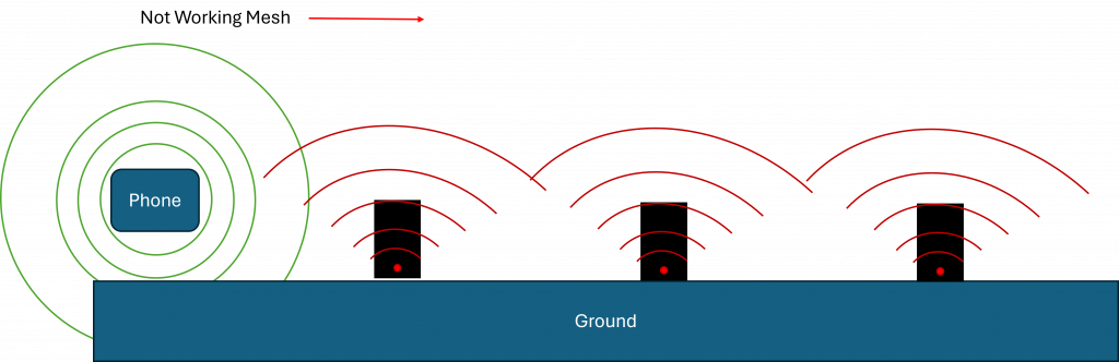
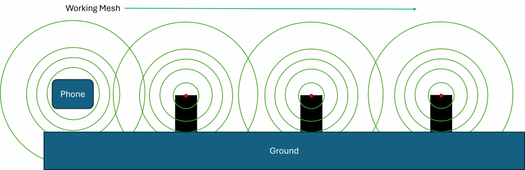
21_Antenna_Design.htmlAntenna Placement in Mesh Systems
For optimal performance, the antenna should be positioned as far from the bottom of the device as possible.
Reasoning (technical):
- The ground (earth or large metal surfaces) acts as a lossy absorber and reflector for RF energy.
- When an antenna is mounted close to the bottom, its radiation pattern is distorted: energy is absorbed by the ground and constructive/destructive interference (multipath) occurs.
- The ground plane effect reduces effective gain, especially at low angles, which are critical for reliable peer-to-peer links in a mesh.
- A low antenna position increases shadowing, so nodes behind obstacles or at further distances can't establish stable connections.
By keeping the antenna higher and away from the ground, the radiation lobes remain more symmetrical, coverage improves, and link quality (RSSI, SNR) stays consistent across the network.
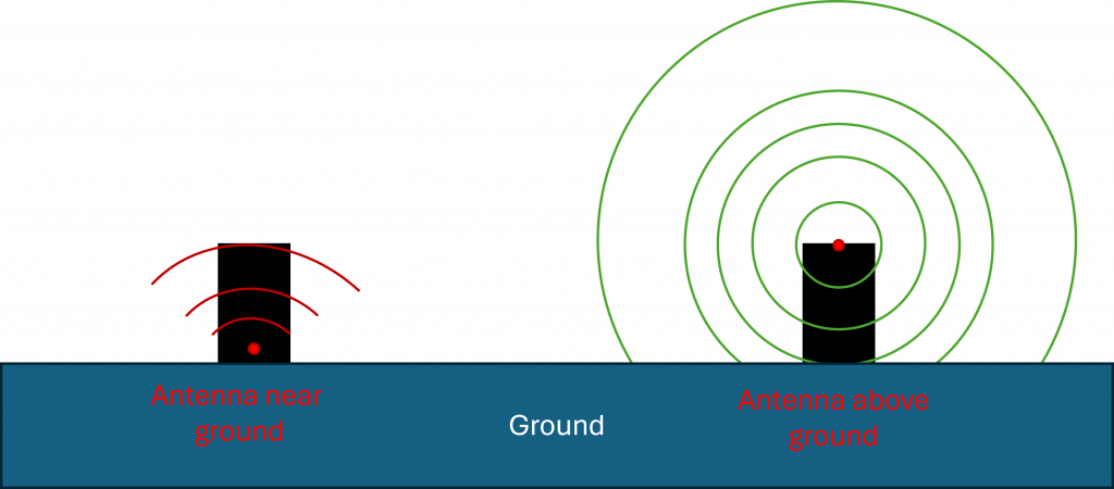
A common practice is to position the antenna beneath the front optics of the device.Because uplights standing on the ground faces upwards all the time.
Antenna Design
Keep-out & enclosure
- Provide a real keep-out volume around the antenna-no metal, ground, or high-epsilonr plastics.
- Avoid metallized paint, carbon-loaded plastic, and water films in front of the antenna.
- If metal is unavoidable, use an on-metal type (PIFA/patch/slot) and treat the metal as the ground plane.
PCB & ground
- Follow the antenna datasheet keep-out exactly; no ground or traces under/around the radiator as specified.
- Solid ground elsewhere with via stitching; no splits under the RF feed.
- For monopoles, ensure adequate counterpoise (ground plane edge length >= lambda/10) or add a tuned ground extension/sleeve.
Feed & matching
- 50 Ohm controlled-impedance feed. Keep the RF path short; avoid stubs and right-angle bends.
- Place a pi-network (shunt-series-shunt) at the feed for tuning in the final enclosure. Start with 0 Ohm/NP and tune by measurement.
- Do not insert random ESD/EMI parts in the RF path; use RF-rated components only.
Cables & noise
Keep coax away from metal and avoid tight bends; strain-relief the connector.
Keep DC/DC converters, crystal cans, fast digital edges, and displays away from the antenna. Route noisy nets on internal layers; guard with ground vias.
Vision Firmware
10_Vision_Firmware.htmlThe Vision Controller is flashed with bootloader firmware first. You can download the newest bootloader here. Make sure you choose the correct bootloader for your application (If you have a preconfigured fixture from us or the bootloader is already flashed you can skip this step):
- Fanstel BT840 (nrf52840) :
https://server.kk-t.eu/api/v1/share/File?file=IQCONTROLLER_VISION_SPI_FBT840_BL1_2_1_SD_7_3_0.hex - Wuerth Orphelia III /Proteus III (nrf52840) :
https://server.kk-t.eu/api/v1/share/File?file=IQCONTROLLER_VISION_SPI_WOIII_BL1_2_1_SD_7_3_0.hex - Fanstel BC833 (nrf52833) :
https://server.kk-t.eu/api/v1/share/File?file=IQCONTROLLER_VISION_SPI_FBC833_BL1_2_1_SD_7_3_0.hex - Abluetech PTR9818 (nrf52840) :
https://server.kk-t.eu/api/v1/share/File?file=IQCONTROLLER_VISION_SPI_FBT840_BL1_2_1_SD_7_3_0.hex - Abluetech PTR9813/PTR9813+ (nrf52833) :
https://server.kk-t.eu/api/v1/share/File?file=IQCONTROLLER_VISION_SPI_FBC833_BL1_2_1_SD_7_3_0.hex
Scan for your fixture in the Vision Control App:
- Open the Vision Control App and make sure you have a working internet connection
- Login with an already existing account or register a new account
- A prepare wizard will open the first time you use the app. Enable your Bluetooth & Location services there. If you accept Bluetooth & Location services it should work out of the box. If an error occurs please inform yourself how to do this on your specific platform. A list of supported and tested devices can be found here: https://iqservice.glp.de/index/SupportedDevices
- Your app will open the Discover page:

- Trigger a Bluetooth scan. A Bluetooth scan can be triggered in two ways depending on your device:
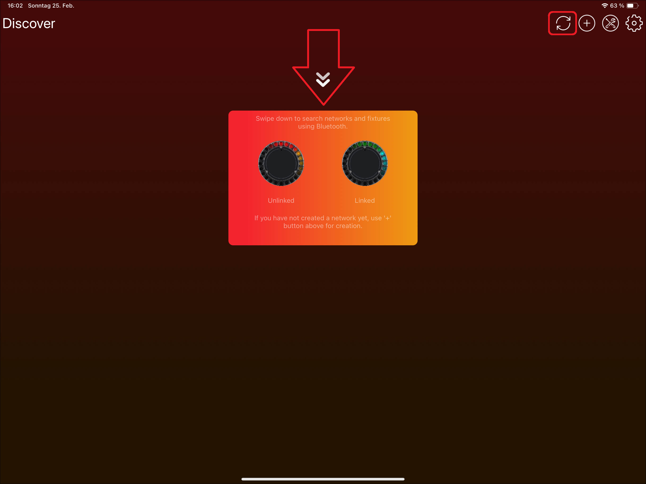
- Tablets: Use either the refresh icon or swipe down:


- Windows: Using the refresh Icon in the top:

- Phones: Swipe down as the icon indicates:

- Tablets: Use either the refresh icon or swipe down:
- Now your device searches for available fixtures using Bluetooth
If you have flashed the bootloader, or the bootloader was already flashed on the Vision module, install the newest Vision firmware using the Vision Control app. If you have a preconfigured fixture from us, skip this step:
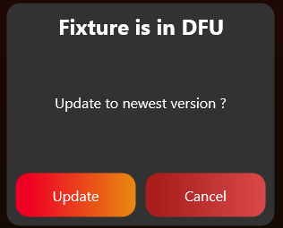
- Press on the "Vision Bootloader" fixture. Do not click the DFU icon; it only selects or deselects the fixture and is not needed for this step.
- The application will ask you to update the Vision firmware. You can update to the newest available version by clicking "Update":
3. SPI Integration
Goal: Connect the fixture firmware to the Vision Controller through the prepared Vision SPI library.
What to implement
- Add the Vision SPI library files to the fixture firmware project.
- Include libVisionSpiInterface.h and use the current Vision API names. Older packages used iQMesh/iqMesh names for the same library.
- Provide the required hardware callbacks for SPI transfer, chip select, and IRQ pin reading.
- Call vision_init with the RDM UID, callbacks, App Control DMX footprint, and DFU support flag.
- Call vision_task regularly from the main loop or scheduler.
- Call the SPI completion/error event after every SPI transfer.
- Detect falling and rising edges on the IRQ pin and forward them to the library.
Important rules
- The fixture main controller is the SPI master.
- SPI mode is CPOL 0, CPHA 0.
- A good SPI baud rate is around 1.125 Mbit/s and should not be much lower.
- Most low-level SPI transaction handling is done by the prepared library.
- The mandatory startup configuration is mainly the correct RDM_ID. Most behavior is handled through RDM and callbacks.
- If optional SPI configuration is used, rewrite it after SYS_RESTARTED.
Test immediately
- Start with the bootloader firmware and validate communication before testing the application firmware.
- Check that the IRQ pin changes are detected correctly and quickly enough.
- Check that vision_task is called regularly and that SPI completion/error events are forwarded.
- Use the communication/debug guide or test preparation workflow if the Vision Controller and main controller do not communicate.
- Only continue to RDM and DMX after basic SPI communication is stable.
Common mistakes
- Debugging RDM or DMX while the SPI event flow is not stable.
- Using a low-priority or incomplete IRQ edge detection implementation.
- Mixing old iQMesh function names with the current Vision library package.
- SPI Interface Introduction (included below)
- SPI Library (included below)
- Bring-up and First Test Setup (included below)
- SPI Configuration (reference link) - Usually not needed when using the prepared SPI library.
- Example Project Software (reference link) - Helpful to understand the example software.
- Example Project Test (reference link) - Helpful to understand the example test workflow.
- Custom Firmware Example - Artery (reference link) - Custom helper.
- Custom Firmware Example - STM32 (reference link) - Custom helper.
- Custom Firmware Adapt Defines (reference link) - Custom helper.
- SPI Protocol Description (reference link) - Low-level protocol detail. Usually handled by the prepared SPI library.
- SPI Operation (reference link) - Low-level transaction detail. Usually handled by the prepared SPI library.
- SPI Commands and Registers (reference link) - Register reference for debugging or custom SPI implementations.
- SPI Interrupts (reference link) - Use if IRQ behavior needs debugging.
- SPI Timing (reference link) - Use if communication timing needs debugging.
SPI Interface Introduction
25_SPI_Interface_Introduction.htmlCommunication between the fixture and the Vision Controller is done through the SPI interface. Therefore the fixtures Main Controller acts as Master and the Vision Controller as Slave.
The interface consists of five 3.3V digital signals:
- IRQ - Interrupt signal. Active low, configurable through the interrupt mask register
- CS - SPI Chip select, active low
- SCK - SPI clock input
- MOSI - SPI data input
- MISO - SPI data output
For SPI interface exists a C library which can be used. You can find it in the chapter Vision SPI Library. The chapter also describes how to implement it. Otherwise use the detailed SPI Specification and build your own SPI Interface.
SPI Library
26_SPI_Library.htmlIt is up to the implementation to provide the hardware interfaces used by the prepared Vision SPI library:
- SPI master interrupt based or using DMA
- External GPIO IRQ interrupt
A good Baudrate for SPI is around 1.125MBits/s, but not much lower. SPI Mode is zero (CPOL = 0, CPHA = 0).
You can find the source code for the library in the Vision External Example or download it from here:
https://kk-t.com/wp-content/uploads/2026/05/VisionSpiLibrary_2026_05_25.zip
Include
Just add all the files to your project. Include libVisionSpiInterface.h and call the necessary functions. The current library uses Vision naming. Older packages and examples used iQMesh/iqMesh; if you compare older material, treat those names as the previous name for the same Vision SPI library.
#include "libVisionSpiInterface.h"Memory Mode
The library supports two memory modes: dynamic allocation and static allocation.
In dynamic allocation mode, memory is allocated at runtime as needed, minimizing overall memory usage.
In static allocation mode, all required memory is defined globally at compile time.
By default, the library uses dynamic allocation.
To enable static allocation, define the compile-time constant VISION_USE_STATIC_ALLOCATION in your project, or uncomment it at the bottom of libVisionSpiInterface.h.
Provide necessary hardware functions
Make sure to provide this external hardware functions:
/* Start SPI transmit and receive interrupt or DMA based */
void HardwareVisionSpiSetTxRx(uint8_t* buf, uint16_t length);
/* Set SPI CS Pin regarding set value */
void HardwareVisionSpiSetCsPin(bool set);
/* Read state of IRQ Gpio Pin */
bool HardwareVisionGpioReadIrqPin(void);
Initialization
For initialization you have to call "vision_init" function. Therefore you have to provide the RDM UID, the necessary callbacks, DMX receive length and if you support device firmware updates.
uint8_t rdmId[6];
uint16_t visionSpecialDmxFootprint= 100; // The footprint used for Vision Control Behavior 255. (App Control)
bool supportDfu = false;
// Register necessary callbacks
vision_callbacks_t callbacks;
// Dfu callback implementation is not needed if dfu is not supported
callbacks.DfuDataReceived = &DfuDataReceived;
callbacks.DfuFlagReceived = &DfuFlagReceived;
// For receiving Dmx frames
callbacks.DmxReceived = &DmxReceived;
// For receiving Rdm frames
callbacks.RdmReceived = &RdmReceived;

// Init Vision SPI library
vision_init(rdmId, visionSpecialDmxFootprint,supportDfu, callbacks);
Change RDM UID
If the serial number is changing and therefore the RDM UID, it is possible to overwrite the RDM UID using:
vision_setRdmId(rdm_id);Provide Task event
In order to process the data its necesary to call "vision_task" whenever there is time. For example in the while loop: (Use a lower priority than the interput routine from SPI and IRQ EXTI)
while (1)
{
  uint32_t timems = HAL_GetTick();
  vision_task(timems);
}
Provide SPI completion event
After completion or if an error occured you have to call "vision_extSpiEvent".
For example using STM32 HAL callbacks:
void HAL_SPI_TxRxCpltCallback(SPI_HandleTypeDef *hspi)
{
	HAL_GPIO_WritePin(CS_GPIO_Port, CS_Pin,GPIO_PIN_SET);
	vision_extSpiEvent(SPI_EVENT_COMPLETION, dmaBufRx, dmaBufLength);
}
void HAL_SPI_ErrorCallback(SPI_HandleTypeDef *hspi)
{
	HAL_GPIO_WritePin(CS_GPIO_Port, CS_Pin,GPIO_PIN_SET);
	vision_extSpiEvent(SPI_EVENT_ERROR, dmaBufRx, dmaBufLength);
}
void HAL_SPI_AbortCpltCallback(SPI_HandleTypeDef *hspi)
{
	HAL_GPIO_WritePin(CS_GPIO_Port, CS_Pin,GPIO_PIN_SET);
	vision_extSpiEvent(SPI_EVENT_ERROR, dmaBufRx, dmaBufLength);
}
Provide GPIO edge detection event
In order to detect edges for the "IRQ" pin, HAL EXTI Callback is used. Because of many controller do not have support for complete edge detection we have to check them in the interrupt. Make sure you detect the falling and rising edge.
.
void HAL_GPIO_EXTI_Callback(uint16_t GPIO_Pin)
{
	if (GPIO_Pin == SPI_IRQ_Pin)
	{
		if (HAL_GPIO_ReadPin(SPI_IRQ_GPIO_Port, SPI_IRQ_Pin))
		{
			vision_extIrqInterupt(SPIEXT_IRQ_EDGE_RISING);
		}
		else
		{
			vision_extIrqInterupt(SPIEXT_IRQ_EDGE_FALLING);
		}
	}
}
Use of RdmReceived callback
The RdmReceived callback has the priority from the Task event. Here you have to decode the RDM message.
In most projects, pass the received data into the same RDM decoder used for wired RDM. Vision does not need a separate second RDM stack. Only add the required Vision custom RDM commands to your existing RDM implementation.
static void RdmReceived(const uint8_t* buf, uint16_t length)
{
	// Handle RDM Data
	RdmDecodeMessage(buf, length);
}
If you have to answer this message write a response directly using:
uint8_t msg[length];
vision_WriteRdm(msg,length);
Use of DmxReceived Callback
The DmxReceived callback has the priority from the Task event. The buffer is released after return from this event. So make sure to copy the data.
The first value in the Vision DMX stream is the Vision Control Behavior. Use it only to interpret the current Vision DMX frame. Do not change the fixture's saved DMX personality, display settings, RDM settings, or settings for other protocols.
For Vision Control Behavior 0, pass the DMX data into the same DMX handling used for wired DMX. For Vision Control Behavior 255, apply the defined App Control defaults for the current frame only.
static void DmxReceived(uint8_t personality, const uint8_t* buf, uint16_t length)
{
	// Handle DMX Data
	if(personality == 255)
	{
		// Use App Control behavior with App Control default settings.
	}
	else if(personality > 0)
	{
		// Use DMX Control with this temporary DMX personality override.
	}
	else
	{
		// Use selected personality from the fixture
	}
}
Use of Dfu Callbacks
The Dfu callback has the priority from the Task event.
static void DfuFlagReceived(vision_dfu_flag_t flag)
{
    // Handle DFU data
	if(flag == VISION_DFUFLAG_STOP)
	{
		// Check if dfu has started
		// Check received data for example using a CRC
		// if anything is good answer with success and initiate the update. There is a timeout about of 10 sec for answering
		vision_WriteDfu(DFU_SUCCESS);
	}
	if(flag == VISION_DFUFLAG_START)
	{
		// Check if dfu has not already started
		// Prepare flash, .. for receiving dfu
		// if anything is good answer with success to start the transmission. There is a timeout about of 10 sec for answering
		vision_WriteDfu(DFU_SUCCESS);
	}
}
static void DfuDataReceived(uint16_t packetNr, const uint8_t* buf, uint16_t length)
{
	// Check if packetNr is correct. Store packet.
	// if something is wrong answer with a error reason
	// vision_WriteDfu(DFU_ERROR_WRONG_PACKETNR);
}
Do not miss:
Make sure you call the following library functions:
- vision_init
- vision_task
- vision_extSpiEvent
- vision_extIrqInterupt
And implement the following callbacks to :
- void HardwareVisionSpiSetTxRx(uint8_t* buf, uint16_t length);
- void HardwareVisionSpiSetCsPin(bool set);
- bool HardwareVisionGpioReadIrqPin(void);
And implement the following callbacks use the data :
- DfuDataReceived
- DfuFlagReceived
- DmxReceived
- RdmReceived
Debug Library – Find Issues
In order to find issues regarding hardware or firmware implementation there is a step by step guide how to debug the library:
Analyse logs of Vision Wireless Controller
To obtain a special firmware version of the Vision Wireless Controller for log collection, please navigate to CUSTOM IMPLEMENTATION Project Artery IC and refer to the chapter Analyse logs of Vision Wireless Controller at the end of the page. The logs can be very helpful during the implementation process.
Bring-up and First Test Setup
66_Test_Preparations.htmlBring-up and First Test Setup
Requirements
For testing the implementation you need one of the following hardware the APP can run:
| Android | iOS | MacOs | Windows | |
|---|---|---|---|---|
| Minimum SDK | Android 10.0 (Api-Level-29) | 12.1 | 10.0.17763.0 | |
| Target SDK | Android 12.0 (Api-Level-32) | – | 10.0.19041.0 | |
| Bluetooth MTU MIN: 230 BYTES | Bluetooth 4.2 REQUIRED | Bluetooth 4.2 REQUIRED | Bluetooth 4.2 REQUIRED | Bluetooth 4.2 REQUIRED |
| NFC | OPTIONAL | OPTIONAL | – | – |
For testing purposes, use our Vision Control app. You have the option of using iOS, Android, or Windows platforms, allowing you the flexibility to choose between a PC, laptop, tablet, or phone – use whichever device suits you best. Additionally, there’s no issue with testing specific features on one device and switching to another during the process.
- Install the following application from one of the possible ways:
- Windows:
- Windows Store: https://apps.microsoft.com/detail/9PN2FRZHH142
Go to Windows Store
- Windows Store: https://apps.microsoft.com/detail/9PN2FRZHH142
- Android:
- Google Play Store: https://play.google.com/store/apps/details?id=de.kkt.Vision
Go to Google Play Store - Huawei Galery: https://appgallery.huawei.com/#/app/C114471795
Go to Huawei Galery - Vision Server: https://server.kk-t.eu/api/v1/Tools/Install?tool=VisionAndroid
- Google Play Store: https://play.google.com/store/apps/details?id=de.kkt.Vision
- iOS / MacOs:
- Apple App Store: https://apps.apple.com/app/vision-control/id6467643102
Go to Apple App Store
- Apple App Store: https://apps.apple.com/app/vision-control/id6467643102
- Windows:
- Make sure the fixture is turned on.
- Make sure the Vision Controller is flashed with firmware. If not, you can download the newest bootloader here. Make sure you choose the correct bootloader for your application (If you have a preconfigured fixture from us or the bootloader is already flashed you can skip this step):
- Fanstel BT840 (nrf52840) :
https://server.kk-t.eu/api/v1/share/File?file=IQCONTROLLER_VISION_SPI_FBT840_BL1_2_1_SD_7_3_0.hex - Wuerth Orphelia III /Proteus III (nrf52840) :
https://server.kk-t.eu/api/v1/share/File?file=IQCONTROLLER_VISION_SPI_WOIII_BL1_2_1_SD_7_3_0.hex - Fanstel BC833 (nrf52833) :
https://server.kk-t.eu/api/v1/share/File?file=IQCONTROLLER_VISION_SPI_FBC833_BL1_2_1_SD_7_3_0.hex - Abluetech PTR9818 (nrf52840) :
https://server.kk-t.eu/api/v1/share/File?file=IQCONTROLLER_VISION_SPI_FBT840_BL1_2_1_SD_7_3_0.hex - Abluetech PTR9813/PTR9813+ (nrf52833) :
https://server.kk-t.eu/api/v1/share/File?file=IQCONTROLLER_VISION_SPI_FBC833_BL1_2_1_SD_7_3_0.hex
- Fanstel BT840 (nrf52840) :
- Scan for your fixture in the Vision Control App:
- Open the Vision Control App and make sure you have a working internet connection
- Login with an already existing account or register a new account
- A prepare wizard will open the first time you use the app. Enable your Bluetooth & Location services there. If you accept Bluetooth & Location services it should work out of the box. If an error occurs please inform yourself how to do this on your specific platform. A list of supported and tested devices can be found here: https://iqservice.glp.de/index/SupportedDevices
- Your app will open the Discover page:

- Trigger a Bluetooth scan. A Bluetooth scan can be triggered in two ways depending on your device:

- Tablets: Use either the refresh icon or swipe down:

- Windows: Using the refresh Icon in the top:

- Phones: Swipe down as the icon indicates:

- Tablets: Use either the refresh icon or swipe down:
- Now your device searches for available fixtures using Bluetooth
- If you have flashed the bootloader, or the bootloader was already flashed on the Vision module, install the newest Vision firmware using the Vision Control app. If you have a preconfigured fixture from us, skip this step:
- Press on the "Vision Bootloader" fixture. Do not click the DFU icon; it only selects or deselects the fixture and is not needed for this step.

- The application will ask you to update the Vision firmware. You can update to the newest available version by clicking „Update“:

- If connection issues occur, reduce the MTU size in App Settings (the gear on top) -> Connection Settings. This is especially helpful for Windows.
- Press on the "Vision Bootloader" fixture. Do not click the DFU icon; it only selects or deselects the fixture and is not needed for this step.
- Check whether the fixture can already be discovered.
- During the first bring-up, the fixture may not be visible immediately if the communication is not working yet.
- If you are testing our example board, turn it on first. It should then be discoverable in the app.
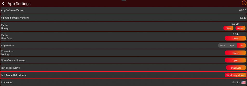
- Set the application to "Test Mode" using the following procedure. This allows you to use and see development fixtures that are not registered yet. If Test Mode is not enabled, only released products can be found and used.
-
Go to „Settings“ by clicking on the gear in the top:

- Click on App Settings:
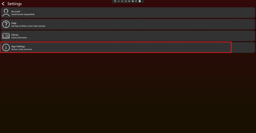
- Tab on the App Software Version label (0.0.5.0) two times. After that a prompt shows up. Type in the PIN "7248". Then the Test Mode will be activated.

-
After successfully enabling the Test Mode, additional help videos will be available. These videos can assist you in better understanding the testing process. Click on „Watch Help Videos“ to see them:
- Go back to the "Discover" page and scan for your fixture.
-
Go to „Settings“ by clicking on the gear in the top:
- Check that the signal LED of the Vision Controller lights up during startup. This only happens after the controller has received the firmware through the app. Also make sure the correct bootloader is flashed on the main module.
- It lights up for 5 seconds every time the controller starts. It does not light up if the controller is either still in Sleep Mode or the wrong firmware is flashed.
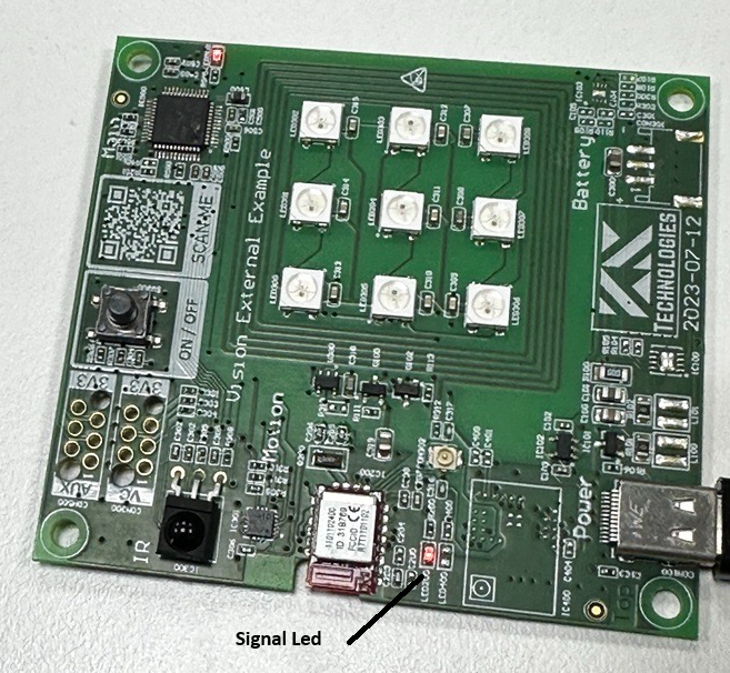
- Make sure the correct bootloader for main module is flashed and your schematic is right.
- Make sure the Vision Controller is in normal operation. Therefore make sure the „FIXTURE_IS_ON“ Pin is set to high. You can find more information in the documentation under System.
- Another issue can be the 32.768khz Crystal. Make sure it is connected and working. Bootloader works without but firmware needs the crystal.
- It lights up for 5 seconds every time the controller starts. It does not light up if the controller is either still in Sleep Mode or the wrong firmware is flashed.
- If your implementation already works make sure you set your input source to "Vision Protocol". Using the RDM Vision command the controller recognizes the input source and will advertise itself using Bluetooth. The Vision Controller only advertises itself when input source is Vision Protocol.
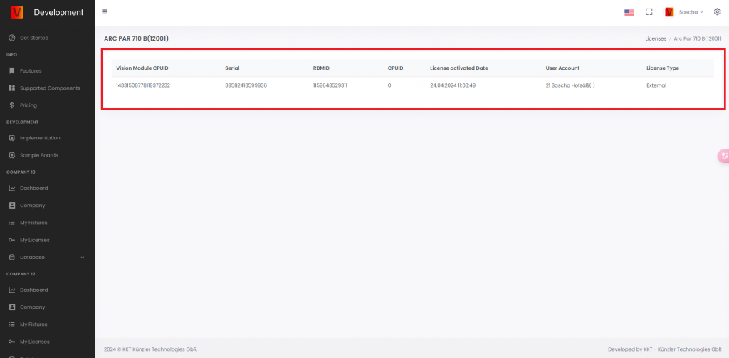
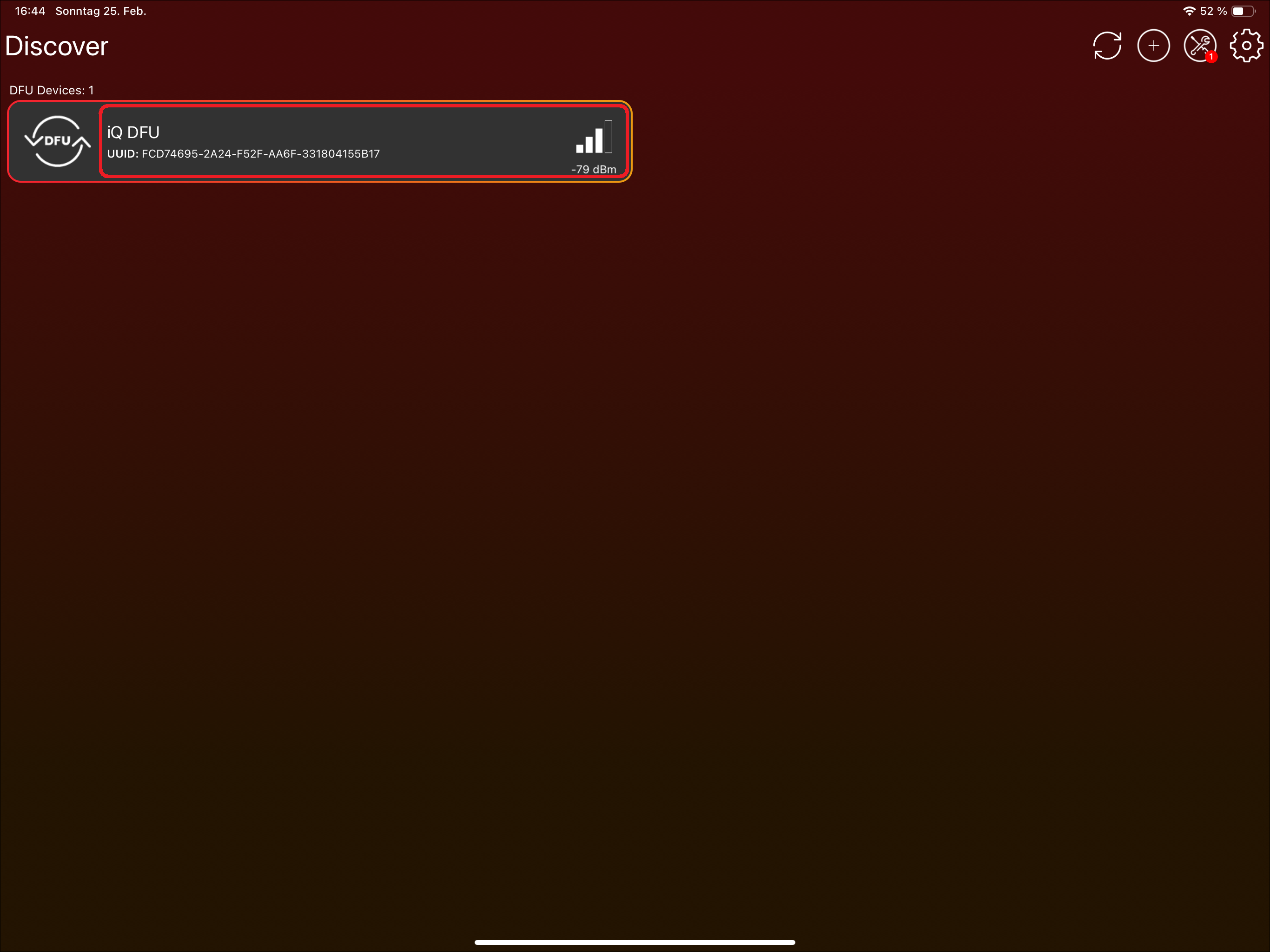
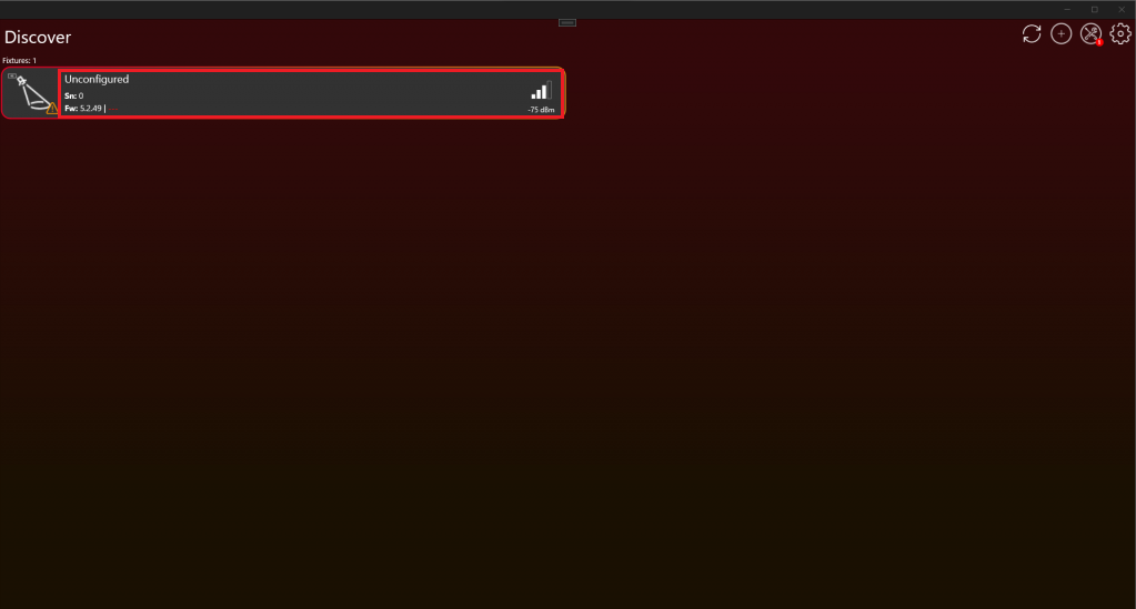
- After scanning, a fixture should be available like this:
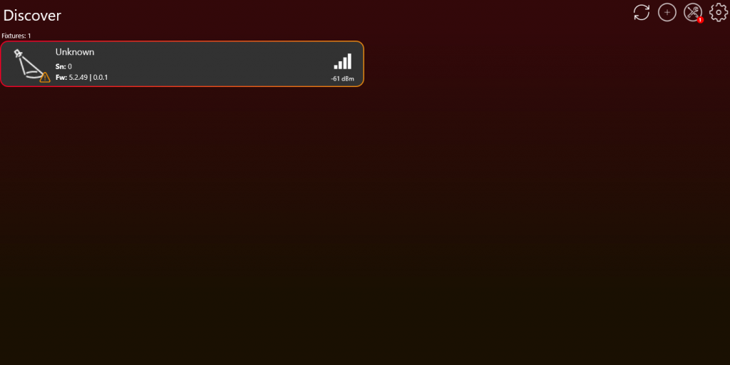
- If the fixture is not available make sure you answer the RDM Vision command correctly. You can find more information in the documentation under Vision RDM -> PIDs -> Command.
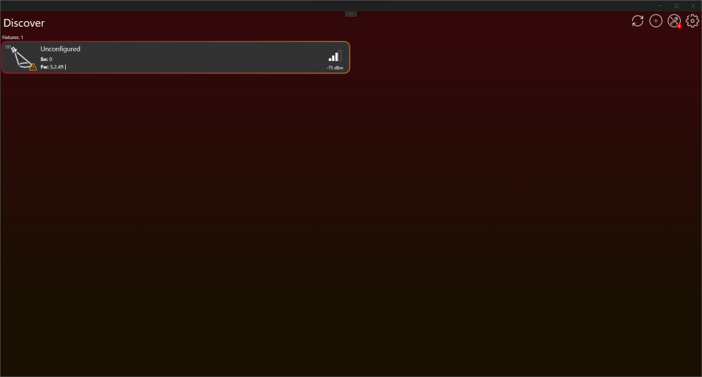
- If the fixture is shown as „Unconfigured“, either the communication interface is not working, or you do not answer the Vision RDM Command correctly. It is also important that Checksum of the Vision RDM command is correct. If you want you can still go on to the next point checking were exactly is the issue.
- After scanning, a fixture should be available like this:
- If this is still the first implementation test, verify the communication before continuing.
- Make sure the SPI communication is working. If you are using the SPI Library, check the last step in the SPI Library chapter to verify that it works as expected: #source-25_SPI_Interface_Introduction
- The main communication uses RDM through the Vision RDM Command. Check whether the Vision GET command is received periodically.
- Make sure all required information is answered correctly.
- After these checks, verify that the Bluetooth advertising signal of your fixture has good quality.
- If you did not discover any fixture make sure your Bluetooth module is available.
- If you have access to a Sample Board, compare the signal strength of your fixture’s Bluetooth advertising with that of the Sample Board. The signal quality of your fixture should not significantly degrade compared to the Sample Board.
- If you don’t have a Sample Board for comparison, ensure the Bluetooth advertising signal quality remains above -60dBm, at a distance of 20cm from your fixture. This threshold represents a very broad minimum standard for signal strength.
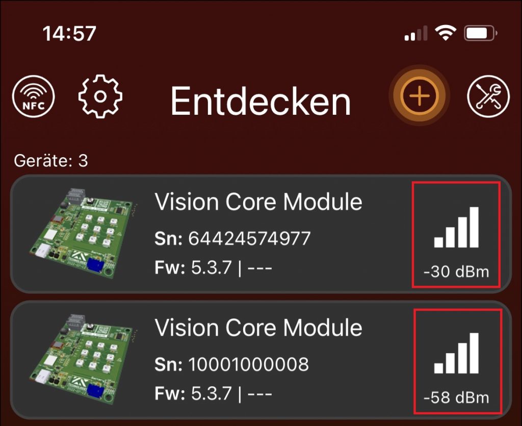
Bluetooth signal quality
- Now pressing on the fixture to connect your device with the fixture. Do not click on the Icon, there you can select and deselect the fixture but we do not need this function currently.
- After your device is connected to the fixture it should look like this. Now you are ready to test!
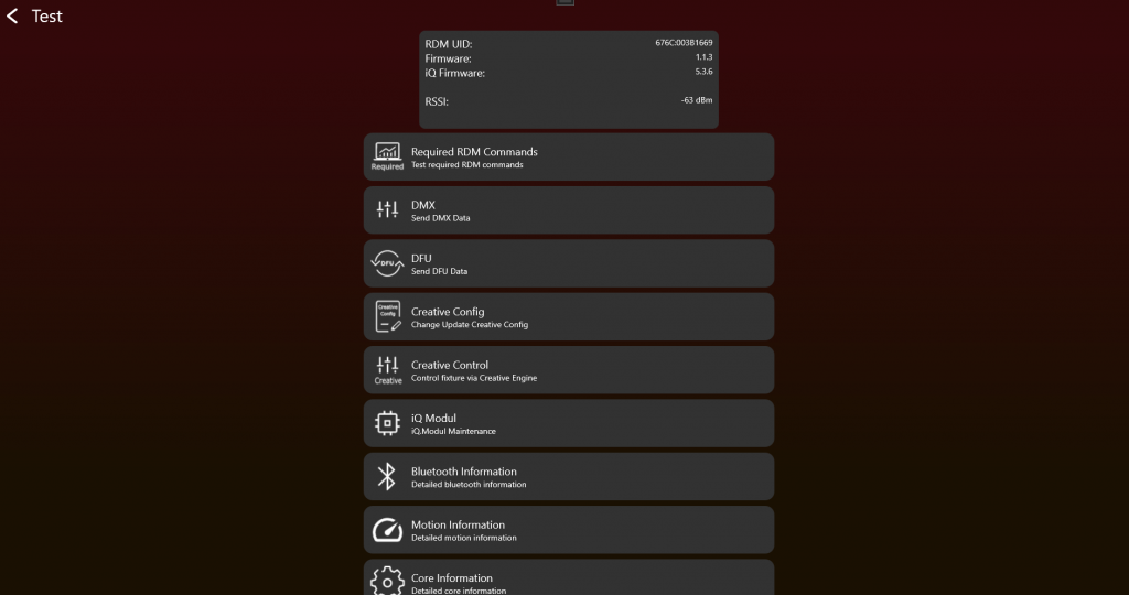
Now you can manually test all the functions needed for the product. When you think all the functions are working as expected, start creating the App Control Configuration for controlling the fixture through App Control:
#source-74_App_Control_Configuration
After that, test your product using the certification tool. Here all functions will be tested step by step:
#source-77_Implementation_Verification_Tool
4. RDM Implementation
Goal: Make the fixture answer the required RDM commands through Vision in the same way it answers wired RDM.
What to implement
- Pass RdmReceived data into the same RDM decoder used for wired RDM whenever possible.
- Return RDM answers through vision_WriteRdm.
- Implement the required standard RDM commands such as device info, device label, factory defaults, DMX personality, DMX start address, identify, reset, power state, and self-test commands.
- Implement the required Vision custom RDM commands: CPID_VISION, CPID_ERROR_CODES, and CPID_WARNING_CODES.
- Expose supported parameters correctly according to the PID requirement page.
- Keep RDM reporting the saved user settings, even when App Control applies temporary defaults to the current Vision DMX frame.
Important rules
- Vision does not use a different RDM protocol. Only the transport layer is different.
- The fixture must always react to RDM commands, even if Vision is not the selected input source.
- Factory default should trigger unlink behavior where required.
- RDM UID and device model information must be correct, especially for OEM products.
- Do not report temporary App Control defaults as saved RDM settings.
Test immediately
- Run the RDM test directly after implementing the required RDM commands.
- Test get and set behavior for device label, factory defaults, DMX personality, DMX start address, identify, and power state.
- Test CPID_VISION behavior, including input source, input state, unlink, and optional features where supported.
- Test error and warning CPIDs.
- Change DMX address and personality through display or wired RDM and confirm RDM over Vision reports the same saved values.
Common mistakes
- Copying a second RDM stack instead of reusing the existing wired RDM implementation.
- Forgetting mandatory standard PIDs because the focus is only on custom Vision CPIDs.
- Letting App Control change saved RDM settings.
- RDM Introduction (included below)
- RDM UID Specification (included below)
- RDM PID Requirements (included below)
- RDM Power State (included below)
- RDM Vision Command (included below)
- Display Menu Requirements (included below)
- Input Sources (included below)
- Test RDM (included below)
- RDM Library (reference link) - Use if you use the prepared RDM library instead of your existing wired RDM stack.
- RDM Error Codes (reference link) - Reference for detailed error reporting.
- RDM Warning Codes (reference link) - Reference for detailed warning reporting.
RDM Introduction
34_RDM_Introduction.htmlThe Vision RDM Protocol is completely based on the RDM Protocol (ANSI E1.20 – 2010). The only difference is the transport layer. The Vision RDM is send and received via the SPI Communication.
The RDM Protocol (ANSI E1.20 – 2010, Entertainment Technology-RDM Remote Device Management Over DMX512 Networks), widely recognized and extensively adopted within the industry for DMX-enabled lighting fixtures, serves as our chosen method for fixture communication. This approach ensures the compatibility and utilization of previously developed libraries, minimizing the necessity for new development.
So Vision is based on standard DMX and RDM concepts. If your fixture already supports wired DMX and RDM, reuse the same DMX handling and the same RDM implementation as much as possible. Vision does not require a separate second RDM stack. Only App Control uses defined fixed DMX behavior so the app can control all fixtures of the same type consistently.
If you do not support RDM, do not hesitate and use our library. This library is found in the next section RDM Vision Library. If you have your own, you can skip this section.
if you need further information about RDM. You can visit their web page https://tsp.esta.org or download there documents here: https://tsp.esta.org/tsp/documents/published_docs.php
RDM UID Specification
36_RDM_UID_Specification.htmlRDM UID Format Specification
The RDM UID must be conform with the RDM Format, unique and must consist of the following information:
- ESTA_Manufacturer_ID
- Unique Id
Format:
- [8 bit – ESTA_Manufacturer_ID]
- [8 bit – ESTA_Manufacturer_ID]
- [8 bit – Unique Id]
- [8 bit – Unique Id]
- [8 bit – Unique Id]
- [8 bit – Unique Id]
To identify a device the RDM Command DeviceInfo with the attribute DeviceInfo.DeviceModelId is required.
Replacement RDM UID
If the fixture has no native RDM support and there is no manufacturer RDM Value , there can be a replacement RDM UID given from us.
- [8 bit – REPLACEMENT_ID]
- [8 bit – REPLACEMENT_ID]
- [8 bit – Unique Id]
- [8 bit – Unique Id]
- [8 bit – Unique Id]
- [8 bit – Unique Id]
REPLACEMENT_ID : 0xFXXX
RDM PID Requirements
37_RDM_PID_Requirements.htmlStandard RDM Commands
The following standard RDM Commands defined in ANSI E1.20 are required and must be implemented.
| RDM Command |
|---|
| PID_DEVICE_INFO |
| PID_DEVICE_LABEL |
| PID_FACTORY_DEFAULTS (During a factory default, an unlink of Vision should be triggered.) |
| PID_DMX_PERSONALITY |
| PID_DMXSTARTADDRESS |
| PID_SENSOR_DEFINITION (No Sensors -> DeviceInfo Sensor Count = 0, PID optional) |
| PID_SENSOR_VALUE (No Sensors -> DeviceInfo Sensor Count = 0, PID optional) |
| PID_DEVICE_HOURS |
| PID_LAMP_HOURS (No Lamp, but led -> Implement it as source hours) |
| PID_LAMP_STRIKES (No Lamp? Not necessary) |
| PID_LAMP_STATE (No Lamp? Not necessary) |
| PID_DEVICE_POWER_CYCLES |
| PID_IDENTIFY_DEVICE |
| PID_RESET_DEVICE |
| PID_POWER_STATE |
| PID_PERFORM_SELFTEST |
| PID_SELF_TEST_DESCRIPTION |
RDM CPID Requirement
The following custom RDM Commands must be implemented.
| RDM Command | Exposed as supported parameter |
|---|---|
| CPID_VISION | No |
| CPID_ERROR_CODES | Yes |
| CPID_WARNING_CODES | Yes |
RDM CPID Optional
The following custom RDM Commands can be implemented to get extended data on the server.
| RDM Command | Exposed as supported parameter |
|---|---|
| CPID_VISION_DATA | No |
| CPID_TOTAL_DEVICE_HOURS | Yes |
| CPID_TOTAL_SOURCE_HOURS | Yes |
| CPID_TOTAL_DEVICE_POWER_CYCLES | Yes |
RDM Power State
38_RDM_Power_State.html
PID Powerstate
Get:
- POWER_STATE_FULL_OFF: Fixture is off. (No answer possible)
- POWER_STATE_SHUTDOWN: Fixture is off. Can go to "POWER_STATE_NORMAL" only using RESET. Fixture still responds to messages.
- POWER_STATE_STANDBY: Fixture is in sleep mode. As less current consumption as possible.
- POWER_STATE_NORMAL: Fixture is in normal operation mode
Set:
- POWER_STATE_FULL_OFF: Fixture turns off
- POWER_STATE_SHUTDOWN: Fixture turns off
- POWER_STATE_STANDBY: Fixture goes to sleep mode. As less current consumption as possible.
- POWER_STATE_NORMAL: Fixture is in normal operation mode
RDM Vision Command
39_RDM_Vision_Command.htmlThis parameter is used to retrieve all necessary information for Vision Controller to work properly.
| Data Type | DS_UNSIGNED_BYTE | PDL Size | Variable (See Protocolversion) |
| Cmd Class | CC_GET | Unit | UNITS_NONE |
| Prefix | PREFIX_NONE | Default | 0x00 |
| Min | 0x00 | Max | 0xFF |
| Description | „VISION“ | ||
GET Command 0xA000
Controller Incoming Command:
| (Port ID) | (Msg. Count) | (Sub-Device) | |
| 0x01-0xFF | 0x00 | 0x0000 (Root) or 0x0001-0x0200 | |
| (CC) | (PID) | (PDL) | |
| GET_COMMAND | VISION (0xA000) | 0x00 | |
| (PD) | |||
Controller Response:
| (Response Type) | (Msg. Count) | (Sub-Device) | |
| ACK | 0x00-0xFF | Copy of Controller SD | |
| (CC) | (PID) | (PDL) | |
| GET_COMMAND_RESPONSE | VISION (0xA000) | Variable (See Protocolversion) | |
| (PD) | |||
| Info Stream | |||
Info Streams:
| Info Stream Protocol Version 1 | ||||
|---|---|---|---|---|
| Index | DataType | Name | Description | Value Definitions |
| 0 | uint8_t | Protocol Version | Describes Protocol Version | 1: Version 1 |
| 1 | uint16_t | DeviceModelId | DeviceModelId from RDM DeviceInfo | |
| 3 | uint64_t | Serial | Serial Number from the fixture in defined Format. Be aware that RDM is Big Endian. | Must be a unique Serialnumber |
| 11 | uint8_t[4] | Vision Controller Firmware Version | Describes Vision Controller Version (Vision). Therefore you can read the SPI register. | [Major,Minor,Patch,Release]Read them from SPI Register. If not available set to zero. This parameter is used only in order to read information over dmx interface. |
| 15 | uint8_t[4] | Vision Controller Bootloader Version | Describes Vision Controller Bootloader Version (Vision)Therefore you can read the SPI register. | [Major,Minor,Patch,Release]Read them from SPI Register. If not available set to zero. This parameter is used only in order to read information over dmx interface. |
| 19 | uint8_t[4] | Fixture Firmware Version | Describes Fixture Version | [Major,Minor,Patch,Release] (Semantic Versioning) Every part is 8 bit and we have added a Release part to indicate if it is an release version or not. Release have to be 255 in order to be publicly available via the server. Otherwise the server will reject your software because it is only an developer version. So you create up to 244 developer versions before doing the release Version with 255. |
| 23 | uint8_t[4] | Fixture Bootloader Version | Describes Fixture Bootloader Version | [Major,Minor,Patch,Release]If no bootloader is available set to zero. |
| 27 | uint8_t[8] | Vision Controller CPU ID | Describes CPU Id from Vision Controller (Vision)Therefore you can read the SPI register. | If not available set to zero. This parameter is used only in order to read information over dmx interface. |
| 35 | uint8_t[12] | Fixture Main CPU ID | Describes CPU Id from Fixture Main Controller | If not available set to zero. This parameter is used only in order to read information over dmx interface. |
| 47 | uint8_t | Battery | Battery state / Level Indicator Info | 1-100: Battery available (chargeable battery for fixture operation): 1 to 100 -> State of charge in %0: No battery available 255: just a small battery for wakeup and configuration of the fixture if Power Supply State is 4 or 5: 0-100 is used as Level Indicator |
| 48 | uint8_t | Power Supply State | Power Supply State / Level Indicator State | 0: No Power (Battery wakeup) 1: Battery Powered 2: Grid Power Supply / AC Power Supply 3: Charging Battery (Not when small battery for configuration is used) If no battery but level indicator needed. For Example haze fluid level, set to one of the following: 4: Level indicator If indication for preparation needed. Like heat up, set it to: 5: Level indicator + Inpreparation |
| 49 | uint8_t | reserved | ||
| 50 | uint8_t | Selected Input Source | Describes selected input source | 0: Vision 1: DMX 2: CRMX / WDMX 3: Artnet 4: SACN 5: GLP DOP 6: IR Remote (Fixture) 7: Manual Mode 8: Auto Mode (Automatic Source Selection with Priority. Take a closer look chapter InputSource) 9 – 252: Reserved 253: Wireless (2.4 GHz) 254: Wireless (Other) 255: Ethernet |
| 51 | uint8_t | Selected Input State | Describes state of selected input source. If selected input source is "Vision", then use Status register information from Vision to derive this value. | 0: Idle (DMX not available,..) 1: Unlinked (CRMX/Vision unlinked,..) 2: Linked (CRMX/Vision linked,..) 3: Active (DMX available, CRMX,..) 4: Active Vision(Vision Active or Master) |
| 52 | uint8_t | Selected Input Quality | Describes signal quality of input source | 0: No quality available 1-100: Quality in % |
| 53 | uint16_t | DMX StartAdress | DMX Startadress of the fixture | 1 – 512 (DMX start address from fixture menu) |
| 55 | uint8_t | DMX Personality | DMX Personality of the fixture | 0: DMX Personality not available 1-255: DMX Personalities(DMX Personality from fixture menu) |
| 56 | uint16_t | DMX Footprint | DMX Channel count of the selected DMX Mode | (DMX Footprint from DMX Personality selected in fixture menu) |
| 58 | uint8_t | Error Count / Warning Count | Error Count of the fixture. | Bit 0-3: Error Count Bit 4-7: Warning Count In Wake Up mode the fixture should show the Error Count from the last session. |
| 59 | uint16_t | Supported Input Sources | Flags for supported input sources | Bit 0: Vision Bit 1: DMX Bit 2: CRMX / WDMX Bit 3: Artnet Bit 4: SACN Bit 5: GLP DOP Bit 6: IR Remote (Fixture) Bit 7: Manual Mode Bit 8: Auto Mode Bit 9 – 15: Reserved Another Source required? Contact us Take in mind that RDM is Big Endian! So it looks like this: [Bit 8-15],[Bit 0-7] |
| 61 | uint8_t | Feature: Sleep Mode | 0: NOT SUPPORTED 1: Supported | |
| 62 | uint8_t | Feature: Battery Shipping Mode | 0: NOT SUPPORTED 1: Supported | |
| 63 | uint8_t | Feature: Emergency Mode | 0: NOT SUPPORTED 1: Off2: On | |
| 64 | uint8_t | Feature: Battery RunTime Selection | 0: NOT SUPPORTED 1: Full Power 2 – 25: Runtime in (Hours +1) | |
| 65 | uint8_t | Feature: Anti-Theft-Mode | 0: NOT SUPPORTED 1: Inactive 2: Ready 3: Active (Alarm triggered) | |
Code Example
typedef enum
{
  RDMVISIONSETTINGSCOMMAND_INPUTSOURCE = 1,
  RDMVISIONSETTINGSCOMMAND_INPUTSTATE = 2,
  RDMVISIONSETTINGSCOMMAND_DISPLAYPOPUP = 3,
  RDMVISIONSETTINGSCOMMAND_EMERGENCYMODE = 4,
  RDMVISIONSETTINGSCOMMAND_BATTERYRUNTIME = 5,
  RDMVISIONSETTINGSCOMMAND_ANTITHEFTMODE = 6,
}rdm_vision_settings_command_t;

typedef enum
{
  RDMVISIONINPUTSOURCE_VISION = 0,
  RDMVISIONINPUTSOURCE_DMX = 1,
  RDMVISIONINPUTSOURCE_CRMXWDMX = 2,
  RDMVISIONINPUTSOURCE_ARTNET = 3,
  RDMVISIONINPUTSOURCE_SACN = 4,
  RDMVISIONINPUTSOURCE_GLPDOP = 5,
  RDMVISIONINPUTSOURCE_IRREMOTE = 6,
  RDMVISIONINPUTSOURCE_WIRELESS2_4GHZ = 253,
  RDMVISIONINPUTSOURCE_WIRELESS2_OTHER = 254,
  RDMVISIONINPUTSOURCE_ETHERNET = 255,
}rdm_vision_inputsource_t;

typedef enum
{
	IQ_POWERSUPPLY_STATE_NOPOWER = 0, // No Power (Battery wakeup)
	IQ_POWERSUPPLY_STATE_BATTERY_POWERED = 1,
	IQ_POWERSUPPLY_STATE_GRID_POWERED = 2,
	IQ_POWERSUPPLY_STATE_CHARGING = 3,
}rdm_vision_power_supply_state_t;

typedef enum
{
	IQ_INPUTSTATE_IDLE = 0, // No Power (Battery wakeup)
	IQ_INPUTSTATE_UNLINKED = 1,
	IQ_INPUTSTATE_LINKED = 2,
	IQ_INPUTSTATE_ACTIVE = 3,
}rdm_vision_input_state_t;

typedef struct  __attribute__((__packed__))
{
  uint8_t protocollVersion;
  uint16_t deviceModelId;
  uint64_t serial;
  uint8_t iqControllerFirmware[4];
  uint8_t iqControllerBootloaderFirmware[4];
  uint8_t fixtureFirmware[4];
  uint8_t fixtureBootloaderFirmware[4];
  uint8_t iqControllerCpuId[8];
  uint8_t fixtureMainCpuId[12];
  uint8_t battery;
  rdm_vision_power_supply_state_t powerSupplyState;
  uint8_t reserved;
  rdm_vision_inputsource_t inputSource;
  rdm_vision_input_state_t inputState;
  uint8_t inputQuality;
  uint16_t dmxStartaddress;
  uint8_t dmxPersonality;
  uint16_t dmxFootprint;
  uint8_t errorCount;
  uint16_t supportedInputSource;
  uint8_t reserved2;
  uint8_t featureShippingMode;
  uint8_t featureEmergency;
  uint8_t featureRuntimeSelection;
  uint8_t featureAntitheftMode;
}rdm_vision_get_response_t;

static void DecodeGetVision(rdm_message_header_t header, uint8_t * msg, uint16_t length)
{
  rdm_answer_t implemented;
  implemented.response = RDM_ACK;
  implemented.reason = NR_UNKNOWN_PID;
  rdm_vision_get_response_t response;
  memset(&response,0,sizeof(response));
  RdmExtGetVision(&implemented,&response);
  if(implemented.response == RDM_ACK)
  {
    response.deviceModelId= __builtin_bswap16(response.deviceModelId);
    response.serial = __builtin_bswap64(response.serial);
    response.dmxStartaddress= __builtin_bswap16(response.dmxStartaddress);
    response.dmxFootprint= __builtin_bswap16(response.dmxFootprint);
    response.supportedInputSource= __builtin_bswap16(response.supportedInputSource);
    SendResponse(header,(uint8_t*)&response,sizeof(response));
  }
  else
  {
    SendNackResponse(header, implemented.reason);
  }
}

typedef enum
{
	IQ_INPUTSTATE_UNLINK = 0,
	IQ_INPUTSTATE_LINK = 1,
}rdm_vision_set_input_state_t;

typedef enum
{
  RDMVISIONBATTERYRUNTIME_FULLOUTPUT = 0,
  RDMVISIONBATTERYRUNTIME_1HOURS = 1,
  RDMVISIONBATTERYRUNTIME_2HOURS = 2,
  RDMVISIONBATTERYRUNTIME_3HOURS = 3,
  RDMVISIONBATTERYRUNTIME_4HOURS = 4,
  RDMVISIONBATTERYRUNTIME_5HOURS = 5,
  RDMVISIONBATTERYRUNTIME_6HOURS = 6,
  RDMVISIONBATTERYRUNTIME_7HOURS = 7,
  RDMVISIONBATTERYRUNTIME_8HOURS = 8,
  RDMVISIONBATTERYRUNTIME_9HOURS = 9,
  RDMVISIONBATTERYRUNTIME_10HOURS = 10,
  RDMVISIONBATTERYRUNTIME_11HOURS = 11,
  RDMVISIONBATTERYRUNTIME_12HOURS = 12,
  RDMVISIONBATTERYRUNTIME_13HOURS = 13,
  RDMVISIONBATTERYRUNTIME_14HOURS = 14,
  RDMVISIONBATTERYRUNTIME_15HOURS = 15,
  RDMVISIONBATTERYRUNTIME_16HOURS = 16,
  RDMVISIONBATTERYRUNTIME_17HOURS = 17,
  RDMVISIONBATTERYRUNTIME_18HOURS = 18,
  RDMVISIONBATTERYRUNTIME_19HOURS = 19,
  RDMVISIONBATTERYRUNTIME_20HOURS = 20,
  RDMVISIONBATTERYRUNTIME_21HOURS = 21,
  RDMVISIONBATTERYRUNTIME_22HOURS = 22,
  RDMVISIONBATTERYRUNTIME_23HOURS = 23,
  RDMVISIONBATTERYRUNTIME_24HOURS = 24,
}rdm_vision_battery_runtime_t;

typedef enum
{
  RDMVISIONANTITHEFT_ON,
  RDMVISIONANTITHEFT_OFF,
  RDMVISIONANTITHEFT_ALARM
}rdm_vision_antitheft_t;


typedef struct
{
   uint8_t protocollVersion;
   rdm_vision_settings_command_t command;
} rdm_vision_settings_stream_t;

static void DecodeSetVision(rdm_message_header_t header, uint8_t * msg, uint16_t length)
{
  rdm_answer_t implemented;
  implemented.response = RDM_ACK;
  implemented.reason = NR_UNKNOWN_PID;
  if(length >= sizeof(rdm_vision_settings_stream_t) + 1)
  {
    rdm_vision_settings_stream_t* stream = (rdm_vision_settings_stream_t*) msg;
    switch(stream->command)
    {
      case RDMVISIONSETTINGSCOMMAND_INPUTSOURCE:
      RdmExtSetVisionInputSource(&implemented,*((rdm_vision_inputsource_t*) &msg[sizeof(rdm_vision_settings_stream_t)]));
      break;
      case RDMVISIONSETTINGSCOMMAND_INPUTSTATE:
      RdmExtSetVisionInputState(&implemented, *((rdm_vision_input_state_t*) &msg[sizeof(rdm_vision_settings_stream_t)]));
      break;
      case RDMVISIONSETTINGSCOMMAND_DISPLAYPOPUP:
      RdmExtSetVisionPopup(&implemented,*((rdm_vision_popup_t*) &msg[sizeof(rdm_vision_settings_stream_t)]) );
      break;
      case RDMVISIONSETTINGSCOMMAND_EMERGENCYMODE:
      RdmExtSetVisionEmergencyMode(&implemented,msg[sizeof(rdm_vision_settings_stream_t)] > 0);
      break;
      case RDMVISIONSETTINGSCOMMAND_BATTERYRUNTIME:
      RdmExtSetVisionBatteryRuntime(&implemented,*((rdm_vision_battery_runtime_t*)&msg[sizeof(rdm_vision_settings_stream_t)]));
      break;
      case RDMVISIONSETTINGSCOMMAND_ANTITHEFTMODE:
		if(*((uint32_t*)&msg[sizeof(rdm_vision_settings_stream_t)]) == 583619)
		{
			 RdmExtSetVisionAntitheftMode(&implemented,RDMVISIONANTITHEFT_OFF);
		}
		else if(*((uint32_t*)&msg[sizeof(rdm_vision_settings_stream_t)]) == 204688)
		{
			 RdmExtSetVisionAntitheftMode(&implemented,RDMVISIONANTITHEFT_ON);
		}
		else if(*((uint32_t*)&msg[sizeof(rdm_vision_settings_stream_t)]) == 388165)
		{
			 RdmExtSetVisionAntitheftMode(&implemented,RDMVISIONANTITHEFT_ALARM);
		}
		else
		{
			implemented.response = RDM_NACK_REASON;
		}
      break;
	   default:
        implemented.response = RDM_NACK_REASON;
      break;
    }
    if(implemented.response == RDM_ACK)
    {
      uint8_t response = 0;
      SendResponse(header,&response,1);
    }
    else
    {
      uint8_t response = 3; // 0 -Ok , 1 - Unknown Command , 2 Err Execution Command, 3 Unsupported command
      SendResponse(header,&response,1);
    }
  }
  else
  {
    SendNackResponse(header, NR_FORMAT_ERROR);
  }
}
SET Command 0xA000
Controller Incoming Command:
| (Port ID) | (Msg. Count) | (Sub-Device) | |
| 0x01-0xFF | 0x00 | 0x0000 (Root) or 0x0001-0x0200 | |
| (CC) | (PID) | (PDL) | |
| SET_COMMAND | Vision (0xA000) | Variable(0-100) | |
| (PD) | |||
| Settings Stream | |||
Controller Response:
| (Response Type) | (Msg. Count) | (Sub-Device) | |
| ACK | 0x00-0xFF | Copy of Controller SD | |
| (CC) | (PID) | (PDL) | |
| SET_COMMAND_RESPONSE | Vision (0xA000) | 1 | |
| (PD) | |||
| uint8_t Status | 0 = OK, 1= Unknown Command, 2 = Error executing Command, 3 = Unsupported Command | |||
Settings Streams:
| Settings Stream Protocol Version 1 | ||||
|---|---|---|---|---|
| Index | DataType | Name | Description | Value Definitions |
| 0 | uint8_t | Protocol Version | Describes Protocol Version | 1: Version 1 |
| 1 | uint8_t | Command Identifier | Command | – |
| 2 | uint8_t[variable] | Data | Data depents on command | – |
| Command | Identifier | DataType | Description | Value Definitions |
|---|---|---|---|---|
| Set Input Source | 0x01 | uint8_t | 0: Vision, 1: DMX, 2: CRMX / WDMX, 3: Artnet, 4: SACN, 5: GLP DOP, 6: IR Remote (Fixture), 7: Manual Mode, 8: Auto Mode, 9 – 252: Reserved 253: Wireless (2.4 GHz) 254: Wireless (Other) 255: Ethernet Another Source required? Contact us | |
| Set Input Source State | 0x02 | uint8_t | 0: Unlink1: Link (trigger) | |
| Show Display Popup | 0x03 | uint8_t [var] | See Command Details | |
| Set Emergency Mode | 0x04 | uint8_t | Set emergency mode on supported fixtures | 0: Off 255: On |
| Set Battery RunTime Selection | 0x05 | uint8_t | Set battery runtime on supported fixtures | 0: Full Power 1 – 24: Runtime in Hours |
| Set Anti-Theft-Mode | 0x06 | uint32_t | Set anti-theft-mode on supported fixtures | 583619: Off 204688: On 388165: Alarm This Command should only be active via VISION and not via DMX RDM for security reasons |
| Set Shipping Mode | 0x07 | — | Set Shipping mode | 255: On |
| Set Serial number | 0x08 | uint8_t[8] uint64_t | Fixture Security Key Serialnumber | Fixture Security Key will be generated from Vision Web Service and can be found on the Fixture Settings Page. |
| Set Device Model ID / Fixture ID | 0x09 | uint8_t[8] uint16_t | Fixture Key DeviceModel/Fixture ID | Individual fixture key. Can be added under RDM Libraries of the Fixture Either RDM Device Model ID or an specific fixture id |
Feature Emergency Mode
Emergency Mode can be enabled and disabled. This setting should be saved, so if the fixture looses power it remembers its state.
If the emergency mode is enabled, the fixture should light up with full output when there is no grid power available. If gridpower (AC) is available then it should behave as in normal operation.
Feature Battery Runtime Selection
Battery RunTime Selection can be enabled and disabled. This setting should be saved, so if the fixture looses power it remembers its state.
If enabled the fixture has to make sure that the battery runtime matches the selection. From minimum 1 hour up to 24 hours. This runtime is defined by a 100% charging state.
A well done implementation is to cut the maximum power output of the fixture. Just calculate the battery capacity, the energy consumption and dim down the light in order to keep the necessary runtime.
Feature Anti-Theft-Mode
Anti-Theft-Mode can be enabled, disabled and triggered. While Anti-Theft-Mode is enabled it should not be possible to turn off the fixture or using a user interface like a display. When Anti-Theft-Mode is triggered the fixture should signal an alarm using visual effects and or sound effects.
This feature can be fully implemented only if the fixture is battery powered. If this feature is active, all user interfaces should be locked. ( Menu locked, Button locked,..) The Vision Controller has information about the current acceleration of the fixture. If that fixture is moved while in anti-theft-mode an alarm will be triggered.
- Use a dynamic colorpattern between red and blue
- Use your internal speaker as siren (optional)
Feature Shipping Mode
Shipping Mode can only be enabled.
If the shipping mode is enabled, the fixture should turn off and cuts off battery power. The fixture can only started again trough gridpower (AC), to ensure a seamless transport experince.
Set Serialnumber / Device Model ID
This function can be used to write a serial number or device model id to the fixture. This function is protected for fixture owners only.
Fixture Security Key will be generated from Vision Web Service and can be found on the Fixture Settings Page.
Display Menu Requirements
54_Display_Menu_Requirements.htmlIn order to get a standardized implementation for the user there must be some definitions. Vision App Control should be designed as an input source like DMX,CRMX or ArtNet.
Name of input Source: „VISION APP“ or when there is not enough characters use „VC APP“.
The VISION APP menu is structured into one action, one optional setting and a group of read-only information items. The table below lists all entries that should be exposed to the user:
| Level 1 | Level 2 | Level 3 | Type | Description |
| VISION APP | Unlink | Action | Unlinks the fixture from the network. Needs to be confirmed by the user. | |
| App Visibility | Vision Active* | Setting (optional) | Vision is selected as Input Source. | |
| Input Inactive | Vision becomes active when no other active Input Source is available. | |||
| Always | Vision is always active. | |||
| Information | State | Information (read-only) | Current link state: Unlinked / Linked / Active / Master / Inactive. | |
| Network Name | Name of the network the fixture is linked to. | |||
| Signal Quality | Signal quality in % (0 - 100). | |||
| UUID | Unique identifier of the fixture. |
Note: The App Visibility setting is optional. If it is not implemented, the fixture should behave as if „Vision Active“ was selected.
Vision-related Fixture Settings (Battery)
The following fixture settings are optional, but recommended because they are surfaced and used by the Vision Control app. If implemented, they should be reachable from the regular fixture menu (typically under General Settings and Fixture Brightness).
| Setting | Options | Type | Description |
| AC Emergency | OFF* / ON | Setting (optional) | Defines fixture behaviour during AC emergency. The Vision app only toggles this setting On / Off. |
| Battery Runtime | OFF* Remaining Time: xx | Setting (optional) | Battery runtime limit disabled. |
| Full battery: 2 h Remaining Time: xx | Target runtime 2 h. | ||
| Full battery: 4 h Remaining Time: xx ... Full battery: 22 h Remaining Time: xx | Target runtime selectable in 2 h steps. | ||
| Full battery: 24 h Remaining Time: xx | Maximum target runtime. |
Full Menu Example
The following example shows how the VISION APP entries can be embedded into a complete fixture menu, alongside common fixture settings. Default values are marked with a „*“.
| Level 1 | Level 2 | Level 3 | Level 4 | Description / Default |
| DMX Settings | DMX Address | 1 - 512 | Default: 1. | |
| DMX Mode | RGB / RGBL / ... | Default: RGB | ||
| Input Source | Wired DMX | Wired DMX input. | ||
| CRMX | Wireless CRMX input. | |||
| Vision App | Make sure CRMX is off in this mode. | |||
| Master / Slave | Set as Master / Set as Slave | Default: Slave. | ||
| Input Settings | Vision App | Unlink | Yes / No | Action - unlinks fixture from network. |
| Visibility (optional) | Vision Active* / Input Inactive / Always | Default: Vision Only. | ||
| Information | State / Network Name | Read-only. | ||
| Signal Quality / UUID | Read-only. | |||
| CRMX | Unlink | Yes / No* | Unlinks CRMX network. | |
| Dimmer Settings | Dimmer Curve | Linear / Square / Square Inv / S-Curve* | Default: S-Curve. | |
| Dimmer Response | Off* / Slow / Middle / Fast / Very Fast | Default: Off. | ||
| Fixture Settings | AC Emergency | OFF* / Hold / Blackout / White / Color Macro | Behaviour on AC emergency. The Vision app only toggles this setting On / Off. | |
| Battery Runtime | OFF* Remaining Time: xx | Battery runtime limit disabled. | ||
| Full battery: 2 h Remaining Time: xx | Target runtime 2 h. | |||
| Full battery: 4 h Remaining Time: xx ... Full battery: 22 h Remaining Time: xx | Target runtime selectable in 2 h steps. | |||
| Full battery: 24 h Remaining Time: xx | Maximum target runtime. | |||
| DMX Fail | Hold* / Blackout | Behaviour on DMX signal loss. | ||
| Factory Defaults | Yes / No | Resets all settings to factory defaults. | ||
| Information | Device Hours | Standard RDM counter (PID 0x0400). Total runtime of fixture. | ||
| Lamp Hours | Standard RDM counter (PID 0x0401). Total LED runtime; the Vision app uses this as LED hours. | |||
| Device Power Cycles | Standard RDM counter (PID 0x0405). Total power cycles. | |||
| RDM ID | Unique RDM device identifier. | |||
| Software Version | Firmware / software version of the fixture. | |||
| Sensors | Sensors like temperature/td> |
Anti-Theft Lockscreen
When the fixture is locked via the Anti-Theft feature, the display should clearly indicate this state and tell the user how to unlock it. The recommended message is:
Anti-Theft is active: Use Vision Control app to unlock
For displays with limited character space, the following short variant can be used instead:
Anti-Theft: Unlock via Vision Control
How to get this information?
Unlink (Action) :
Using the Vision SPI Library this function can be found in „libVisionSpiInterface.h“ and is called „vision_triggerUnlink“. This will unlink the fixture from an network created through the Vision App.
State (Information)
Using the Vision SPI Library this function can be found in „libVisionSpiInterface.h“ and is called vision_getStatusFlags. The return type is vision_status_flags_t. Inside this type you can find the vision_status_t which is the needed information.
Network Name (Information)
Using the Vision SPI Library this function can be found in „libVisionSpiInterface.h“ and is called vision_getInformation.The return type is vision_information_t which includes a 12 Bytes long network name.
Signal Quality (Information)
Using the Vision SPI Library this function can be found in „libVisionSpiInterface.h“ and is called vision_getInformation.The return type is vision_information_t which includes a signalQuality. 0 - 100: Quality in %
UUID (Information)
Using the Vision SPI Library this function can be found in „libVisionSpiInterface.h“ and is called vision_getInformation.The return type is vision_information_t which includes a uuid.
Input Sources
55_Input_Sources.htmlVision requires some Source switching Logics to work as expected.
Therefore the fixture must use different input sources if it has different signal inputs. These input defines which signal is active at a time.
Vison supports:
0: Vision
1: DMX
2: CRMX / WDMX
3: Artnet
4: SACN
5: GLP DOP
6: IR Remote (Fixture)
7: Manual Mode
8: Auto Mode (Automatic Source Selection with Priority)
9 - 252: Reserved
253: Wireless (2.4 GHz)
254: Wireless (Other)
255: Ethernet
Auto Mode (Automatic Source Selection)
This mode is used to automatically switch between protocols without changing the input source. This mode should behave as follow:
Priority: 1. DMX, 2.WDMX, 2: Vision App Control
Whenever a source gets active with a higher priority DMX should be used from that source and wireless radio protocols may turned off as long as this source stays active.
Idle: WDMX and Vision App Control should be active
DMX Active: WDMX and Vision sould be off. Turn off WDMX chip, Vision will automatically handle this usecase, you just have to answer with correct response in RDM CPID Vision (50:Selected Input Source, 51:Selected Input State). CPID Vision
WDMX Active: Vision sould be off. Vision will automatically handle this usecase, you just have to answer with correct response in RDM CPID Vision (50:Selected Input Source, 51:Selected Input State). CPID Vision
Vision Active: WDMX must turned off.
Test RDM
68_Test_RDM.html- After enabling the Test Mode and connecting to the fixture it should look like this. To test RDM Commands click on „Required RDM Commands“:
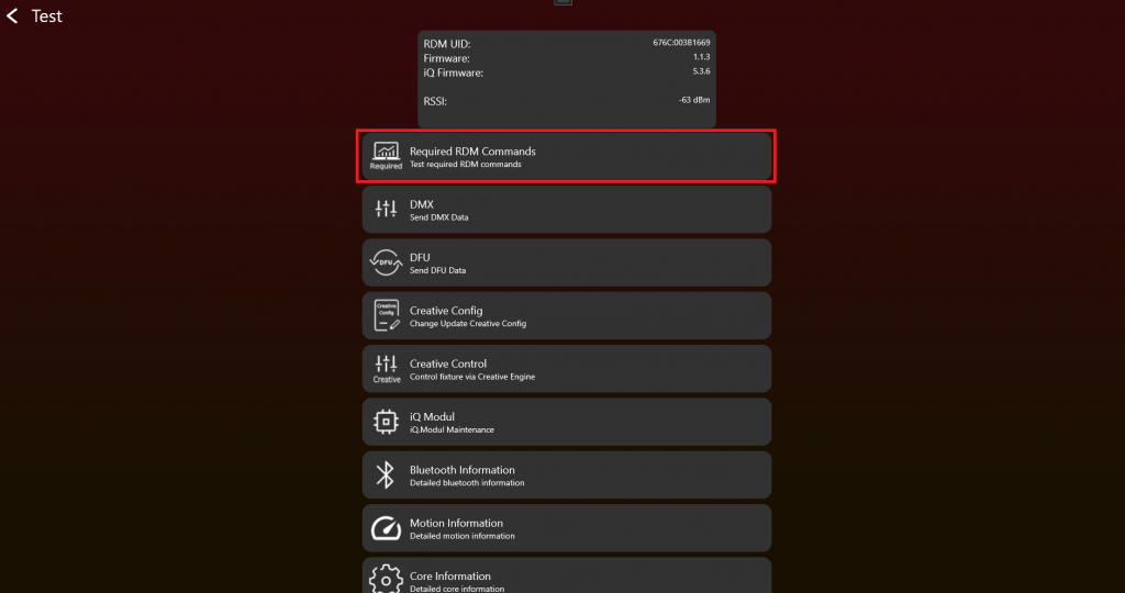
2. Simply click on a Get / Set button and RDM commands will be send to your fixture. A result will be shown. Check for each RDM command the result.
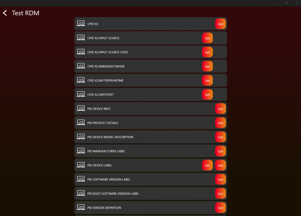
3. If you get a correct response it should look like this:
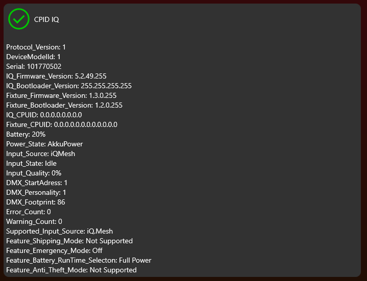
4. Repeat this step for each RDM command
5. DMX and App Control
Goal: Implement normal DMX Control and App Control behavior without confusing them with saved fixture settings.
What to implement
- Use DmxReceived to receive the Vision DMX stream.
- Read the first value as Vision Control Behavior.
- For Vision Control Behavior 0, pass the DMX data into the same DMX handling used for wired DMX.
- For Vision Control Behavior 255, apply App Control defaults for the current frame only.
- For values 1-254, support legacy Vision DMX Adapter behavior only if required.
- Write the fixture's physical DMX input back to Vision with WRITE_DMX when Vision is not the selected input source.
Important rules
- Vision Control Behavior 0 means DMX Control with the fixture's saved DMX start address, DMX personality, and user settings.
- Vision Control Behavior 255 means App Control with fixed defaults such as DMX start address 1 and the required App Control personality.
- App Control must not modify saved display settings, saved DMX settings, RDM settings, or settings for other protocols.
- Fixtures of the same type must behave consistently during App Control.
- RDM shall still report saved user settings, not temporary App Control defaults.
- Values 1-254 are legacy behavior for the Vision DMX Adapter only.
Test immediately
- Test Vision Control Behavior 0 with DMX start address 1 and another start address such as 10.
- Test different saved DMX personalities and confirm behavior matches wired DMX.
- Test Vision Control Behavior 255 and confirm the fixture ignores saved DMX start address for the current frame.
- Confirm App Control uses the required fixed personality and predictable color behavior.
- If supporting the Vision DMX Adapter legacy behavior, test Vision Control Behavior 1 and 2 as temporary personality overrides.
Common mistakes
- Calling App Control a DMX mode and making customers think it is a saved fixture DMX personality.
- Changing the fixture's saved DMX personality when a Vision frame requests temporary behavior.
- Using saved RGB/RGBW/RGBL fixture settings in App Control when the app requires one consistent behavior.
- DMX Introduction (included below)
- DMX Frame (included below)
- DMX Personality Requirement (included below)
- Test DMX (included below)
DMX Introduction
47_DMX_Introduction.htmlThe Vision DMX Protocol is completely based on DMX 512. The only difference similiar to the Vision RDM Protocol is the transport layer and the first data byte in the data stream . The Vision DMX is received via the SPI Communication.
DMX512 (E1.11 - 2008, USITT DMX512-A) is a standard for digital communication networks that are commonly used to control lighting and effects.
DMX512 Protocol
DMX512 is a digital communication standard that sends control data over a single cable to multiple devices, like dimmers, spotlights, and moving heads, typically used in theatrical, concert, and event lighting. The data is sent in packets with up to 512 separate channels, each controlling a specific aspect of the lighting fixtures.
DMX Personalities
„DMX Personalities“ refer to the different configurations that a DMX-controllable device can have. Each personality represents a different mode of operation, affecting how many channels a device uses and what each channel controls. For example, a lighting fixture might have one personality that uses three channels for red, green, and blue lighting control, and another personality that uses four channels like Master Dimmer, red, green,blue.
DMX Start Address
The start address is the first channel number that a device listens to on the DMX network. It defines where in the sequence of 512 channels a device’s control begins. For instance, if a device is set to a start address of 101, and it operates in a personality using 5 channels, it will use channels 101 to 105. Setting the correct start address is crucial for the proper operation of the lighting system, as it ensures that the correct data is sent to the intended devices.
DMX Footprint
The „footprint“ refers to the number of consecutive DMX channels a device uses based on its current personality. A device with a larger footprint will use more channels, which allows for more granular control over various functions of the device. The footprint size can vary depending on the device’s complexity and the personality selected. For instance, a simple dimmer might have a footprint of 1, while a sophisticated moving head could have a footprint of 20 or more channels.
This means that Vision DMX follows the same principles as standard DMX512 in terms of DMX Personalities, Start Address, and Footprint. However, the key difference lies in the method of data transmission; instead of the typical DMX512 protocol, Vision DMX uses SPI (Serial Peripheral Interface) for receiving data packets. This is a common hardware interface used for short-distance communication, particularly in embedded systems.
DMX Frame
48_DMX_Frame.htmlThe Vision DMX data stream is defined as the following:
| data[0] | data[1] | data[2] | data[3] | ... | data[512] |
|---|---|---|---|---|---|
| Vision Control Behavior | dmx[1] | dmx[2] | dmx[3] | ... | dmx[512] |
Vision Control Behavior = 0 -> DMX Control.
When Vision Control Behavior is set to 0, the fixture shall behave like it is controlled by a normal DMX stream.
The fixture shall use the currently selected DMX settings, including for example:
- DMX mode
- DMX start address
- fixture configuration
- color mixing settings
- other user-selected fixture settings
In this mode, the behavior shall be identical to normal DMX operation.
Vision Control Behavior == 255 -> App Control.
The fixture shall use defined App Control behavior according to the Vision DMX Personality Requirement.
In this mode, the fixture shall ignore user-selected DMX settings for the current Vision DMX data stream and instead use fixed, app-optimized default values.
This includes, for example:
- All fixtures of the same type shall behave consistently during app control
- DMX start address shall be
1 - DMX mode shall match the required Vision DMX personality
- color mixing behavior shall be fixed and predictable
- the fixture shall not switch between RGB, RGBW, RGBL, or similar modes based on fixture settings
This is important because fixtures must not behave differently when controlled through the Vision app.
The fixture shall not modify any internal user settings, display settings, saved DMX settings, or settings used by other protocols.
The App Control defaults are only applied internally for the Vision DMX data stream.
RDM shall still report the user-selected fixture settings, not the temporary App Control defaults.
This function is used that the app can control the fixture in a defined state without manipulating the settings of the fixture.
Example using the Vision SPI Library
- Data[0]: Vision Control Behavior
- Data[1-512]: DMX (DMX Data[0..511])
In the example this is already separated:
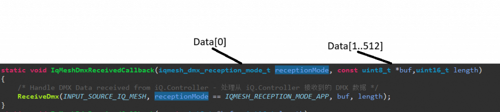
Example Fixture Implementation:
Personalities of your fixture:
- 1: Simple (Length 5)
- 2: Advanced (Length 10)
- 3: Single Pixel Control (Length 50)
- App Control Personality: (Not exposed in RDM) -> Single Pixel Control (Length 50)
App Control Settings:
Default App Control Settings: Dimmer Curve Linear, Dimmer Speed fast (snap)
Current Example
Selected DMX Address: 10
Selected DMX Personality: 2
Selected Dimmer Curve: Quadratic , Selected Dimmer Speed slow
Behavior:
- Vision Control Behavior = 0
- DMX Data[9] DMX Personality[2]
- Dimmer Curve Quadratic, Dimmer Speed slow
- Vision Control Behavior = 255 -> App Control with fixed App Control defaults
- DMX Data[0] DMX Personality[3]
- Dimmer Curve Linear, Dimmer Speed fast (snap)
DMX Personality Requirement
49_DMX_Personality_Requirement.htmlVision App Control Requirement
There is a control footprint requirement for controlling the fixture with the Vision Control App. The app uses the reserved Vision Control Behavior 255, called App Control.
React to the Vision Control Behavior from the Vision DMX stream as described in the interface section. Value 255 is reserved for App Control. In this mode, use fixed App Control defaults so all fixtures of the same type behave consistently regardless of any user setting.
Master Dimmer / Shutter is not required. All pixel will controlled individually prefered with 16 bit control.
Default Behavior:
LED Control (Color)
RGBxx 16 bit linear control over all pixels is recommended. On single pixel controlled fixtures every pixel should be controllable. RGBxx control should not be faded / delayed, because we use these channels also for our synchronized strobes. For smoothing the dimming, please use our example code.
LED Control (White)
White 16 bit linear control over all pixels is recommended. On single pixel controlled fixtures every pixel should be controllable. Control should not be faded / delayed. For smoothing the dimming use our code template.
Pan & Tilt
| PanTilt | DMX Value | Slot Style | Note | |
| Tilt coarse | 0 | 65535 | fade | |
| Tilt fine | ||||
| Pan coarse | 0 | 65535 | fade | |
| Pan fine | ||||
Pan & Tilt Rotation Speed
| Pan & Tilt Rotation Speed | DMX Values From (8/16 bit) | DMX Values To (8/16 bit) | Description |
|---|---|---|---|
| No rotation | 0 / 0 | 0 / 255 | no rotation |
| Rotation Speed Clockwise (CW) Fast > Slow | 1 / 256 | 127 / 32767 | 1/256: fastest rotation speed CW 127/32767: slowest rotation speed CW |
| No rotation | 128 / 32768 | 128 / 33023 | no rotation |
| Rotation Speed Counter-Clockwise (CCW) Slow> Fast | 129 / 33024 | 255 / 65535 | 129/33024: slowest rotation speed CCW 255/65535: fastest rotation speed CCW |
Value 0 or 128:
Rotation is disabled. The fixture's Pan and Tilt position is defined exclusively by the standard Pan and Tilt control channels.
Values 1-127 and 129-255:
Rotation is enabled. The fixture performs a continuous rotation at a speed according to the applied value.
Transition behavior (Rotation -> Position):
When the value changes from a rotation range (1-127 or 129-255) to 0 or 128, the fixture shall smoothly transition back to the standard Pan and Tilt position defined by the Pan and Tilt control channels. The movement should continue in the current direction of rotation (if possible) and should not stop abruptly before moving to the standard Pan and Tilt position.
Focus
| Focus | DMX Value | Slot Style | Note | |
| Focus coarse | 0 | 65535 | fade | near to far / please also disable or enable focus tracking feature |
| Focus fine | ||||
Zoom
| Zoom | DMX Value | Slot Style | Note | |
| Beam Angle | 0 | 255 | fade | narrow [000] ... wide [255] |
Fog
| Zoom | DMX Value | Slot Style | Note | |
| Fog intensity | 0 | 255 | fade | no fog[000] ... 100% fog[255] |
Fan
| Fan | DMX Value | Slot Style | Note | |
| Fan intensity | 0 | 255 | fade | no fan[000] ... 100% fan[255] |
More components required? Please contact us. We will add the necessary components.
Test DMX
69_Test_DMX.html- After enabling the Test Mode and connecting to the fixture it should look like this. To test DMX click on „DMX“:
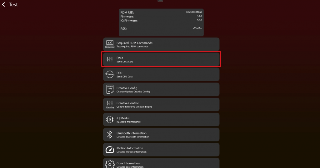
2. Choose the "Vision Control Behavior" and set "DMX Values" via the sliders. Test DMX Control with different "DMX start addresses" and "DMX Personalities" (sometimes also called "DMX Modes") to make sure everything works as expected. The "Change Personality" function changes the temporary DMX Personality used for the current Vision DMX stream.
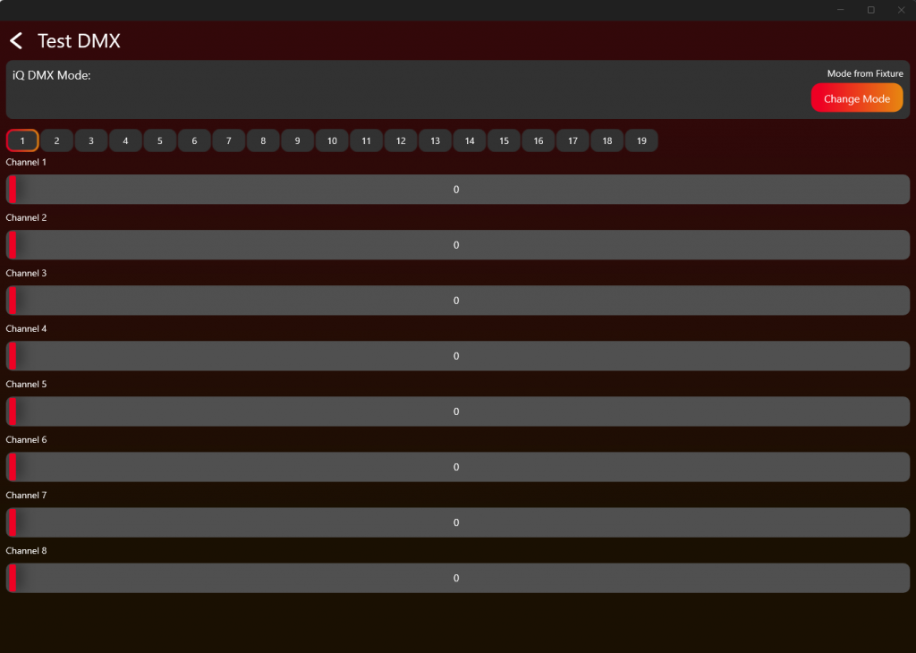
Test the DMX Personality 0, 1-x and 255 as described in the Table and the DMX Chapter.
| Vision Control Behavior | Control behavior |
|---|---|
| 0 | DMX Control using the fixture's saved DMX settings |
| 1 | Legacy / Vision DMX Adapter only: DMX Control using DMX Personality 1 for this frame only |
| 2 | Legacy / Vision DMX Adapter only: DMX Control using DMX Personality 2 for this frame only |
| ... | ... |
| 255 | App Control using fixed App Control settings. Read DMX from the beginning of the stream independent from DMX start address. |
6. App Control Configuration
Goal: Define the fixture data the app needs to control the product correctly through App Control.
What to implement
- Create the App Control Configuration after DMX and App Control behavior are working.
- Define only the components the fixture actually supports.
- Define pixel count, pixel positions, color components, white, zoom, focus, pan/tilt, smoke, or other supported components as needed.
- For color components, provide the required spectral data and illuminance or luminous flux values where required.
- Save the App Control Configuration as a file and write it to the fixture for testing.
- Upload the App Control Configuration during release preparation for the fixture.
Important rules
- App Control Configuration was previously called Creative Configuration or Creative Config. Older screenshots, app versions, filenames, and URLs may still use the old name.
- Each fixture type needs an App Control Configuration to be controlled through App Control.
- For App Control on controllable fixtures, use Vision Control Behavior 255.
- If a fixture has multiple pixels but cannot control them individually, treat it as one full fixture pixel.
- Upload only components the product really supports.
Test immediately
- Write the App Control Configuration to the fixture.
- Open the App Control test and confirm only supported components appear.
- Move sliders or controls for every configured component and confirm the fixture reacts correctly.
- Test shutter performance and color behavior.
- If the fixture cannot be controlled correctly, return to the App Control Configuration and fix the component setup.
Common mistakes
- Creating the App Control Configuration before DMX and App Control behavior are stable.
- Configuring components that the fixture does not actually support.
- Confusing the App Control Configuration with a normal saved DMX personality.
- App Control Configuration (included below)
- App Control Test (included below)
- Create App Library - Create Fixture (reference link) - Use later when uploading the final App Control Configuration for release.
- Production - Update Vision Module (reference link) - Use later when updating modules in production.
App Control Configuration
74_App_Control_Configuration.htmlAfter enabling the Test Mode and connecting to the fixture it should look like this. To create an App Control Configuration, click on "App Control Configuration":
Legacy naming: App Control Configuration was previously called Creative Configuration or Creative Config. Older screenshots, app versions, file names, or URLs may still use the old name.
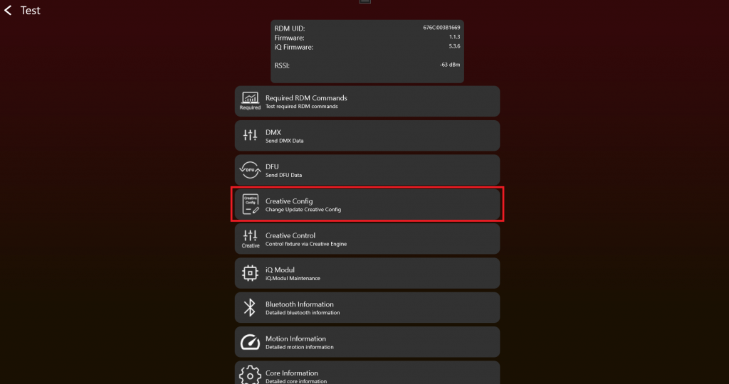
If everything works so far, the fixture can be prepared for App Control. Here you can create, load, or write an App Control Configuration. Each fixture type needs an App Control Configuration to be controlled through App Control. The App Control Configuration consists for example of the number of pixels, their position, and related fixture control data.

Start by creating an App Control Configuration. Press Create App Control Configuration.
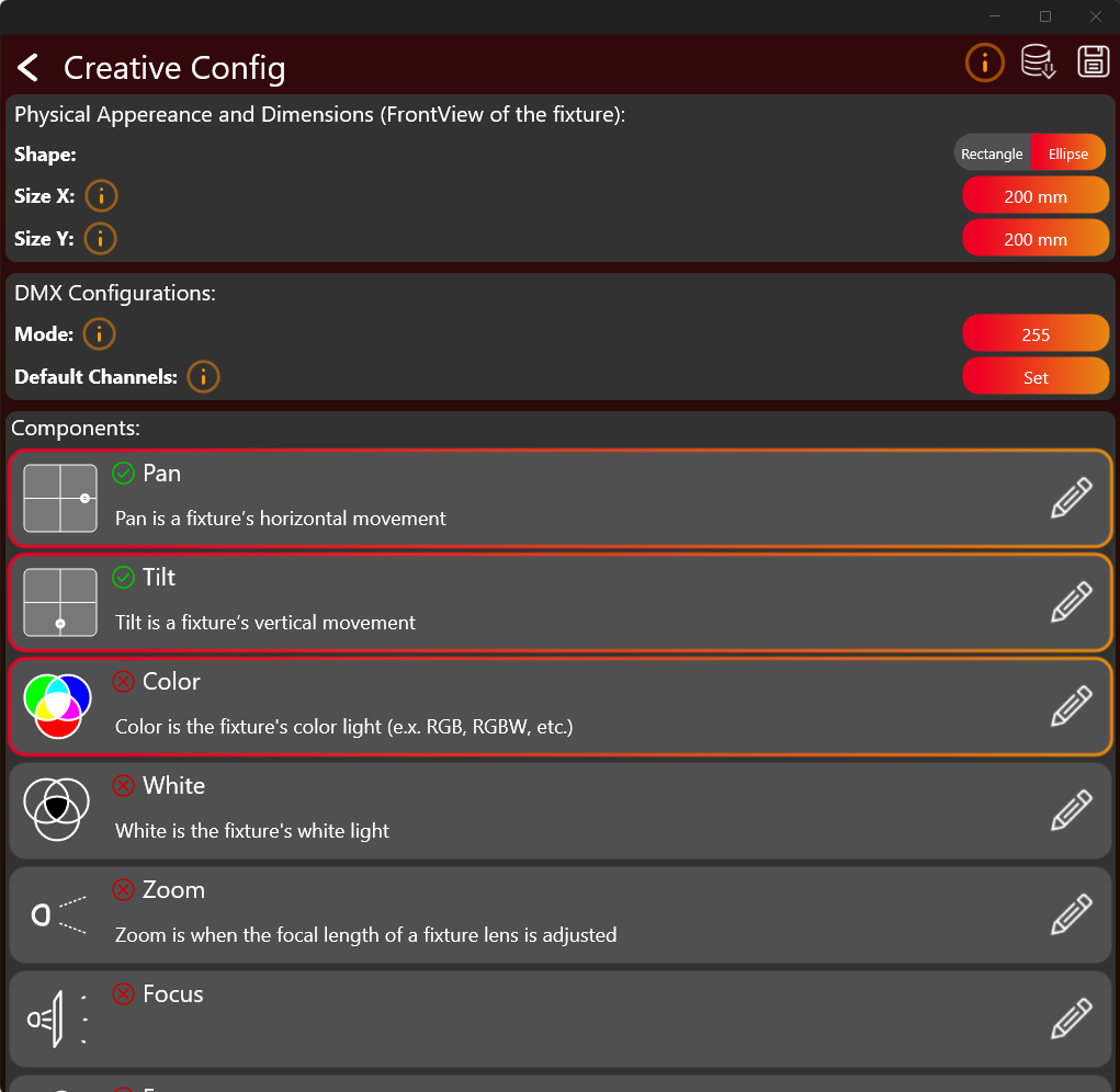
Click on the buttons to set the desired values. Select and configure each required component (like Pan, Tilt Color, White, Zooms, Focus, Smoke etc). Tapping on the whole frame selects the component. Select only components your fixture actually supports. By clicking on edit pencil on the right the configuration can be edited. A green checkmark indicates that the configuration for this component have been done.
Use the orange info „i“ buttons to get more information to the regarding topic.
After finishing the configuration you should save it as a .json file and write it to the fixture via the buttons on the top.
Color Component
The Color Component can be quite challenging to configure. So there are some more detailed information explained here. After pressing the edit button of the Color Component a new window appear which looks like this:
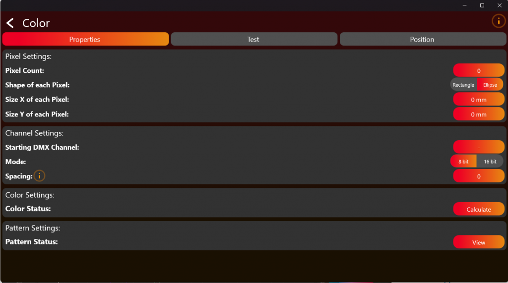
Here you have to define the pixel count of the fixture. Just the pixel which are controllable through DMX. Then put in the DMX information on how to control the LED’s. After configuring have to test and Position your pixels using the tabs in the top. Click on Calculate to get to the Color Settings.
Now we come to the difficult part. The Color Settings:
Select the Color Count of the fixture. RGB for example has 3 colors. For the next steps we need the Color Information:
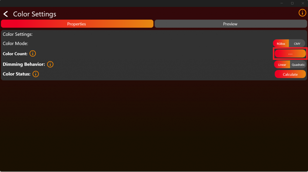
Therefore we need the spectral output of each Color at full in brightness relative to each other. For this kind of measurement you could use any spectrometer which has a resolution of 1nm over the Range from 380nm to 780nm. For Example the UPRTEK MK350N Premium.
Therefore place the fixture in a appropriate distance to the spectrometer. Make sure the mixing of the colors from the fixture on the detector is as good as possible. Also measure the colors with an appropriate cooler temperature when there is no temperature compensation on the fixture side. Measure each Color independent as you can see in the following picture. In this example it is done via a RGBW LED Source. We support up to 6 Color LED Sources.
The following example is with the UPRTEK MK350N Premium:
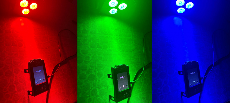
After measure you should get the spectral response of the color relative to the others. Like this:
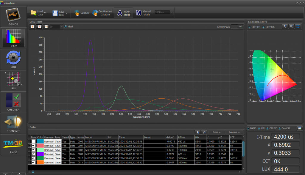
The results of the UPRTEK MK350N Premium will be saved in an Excel file. Refer to the provided document for an example format:
The necessary illuminance value is LUX (lx), in our example, it is approximately 1515.47 lx.
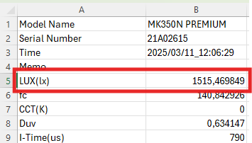
In the next step, extract the required spectral data from 380 nm to 780 nm (mW/m^2). Refer to the image for an example:
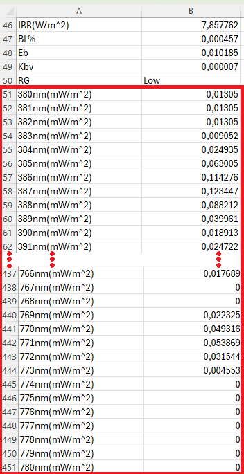
Copy the values displayed within the blue square:
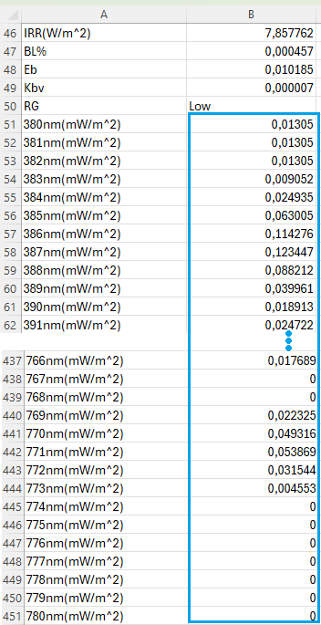
Insert the values into a new .txt file while ensuring the required format is met. For better understanding, refer to the example file.
Format requirements:
- The decimal seperator must be a „.“ (dot). Values must be separated by a „,“ (comma). All values should be arranged in a single line without line breaks.
This can be achieved for example in Notepad++ using Find and Replace function:
- Replace „,“ with „.“
- Replace „\r\n“ with „,“ (Ensure Search Mode is set to Regular expressions).
In the picture below it is a configuration for 3 Colors, for example RGB. From the available options, select „Custom“, then you will be prompted to upload the .txt file containing the spectral data:
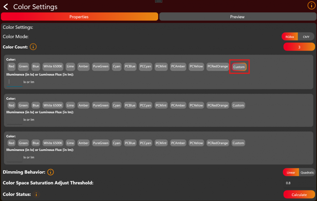
You can enter either the illuminance in lux (lx) or the luminous flux in lumens (lm) for each color.:
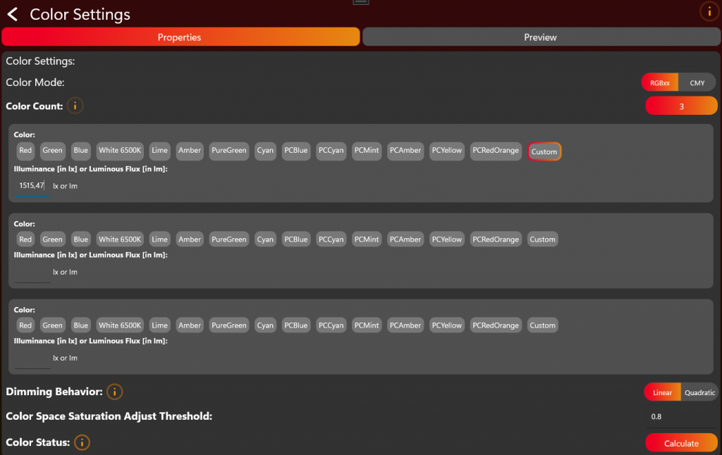
Repeat and upload the spectral data and enter the illuminance value for all LED colors.
When finished press Calculate and wait until the calculation is finished. Depending on the ColorCount this may take some time.
Save and Write App Control Configuration
Now you have finished the App Control Configuration and we are back on the first editing page. In the top right, save the configuration as a file or send it directly to the fixture for testing:
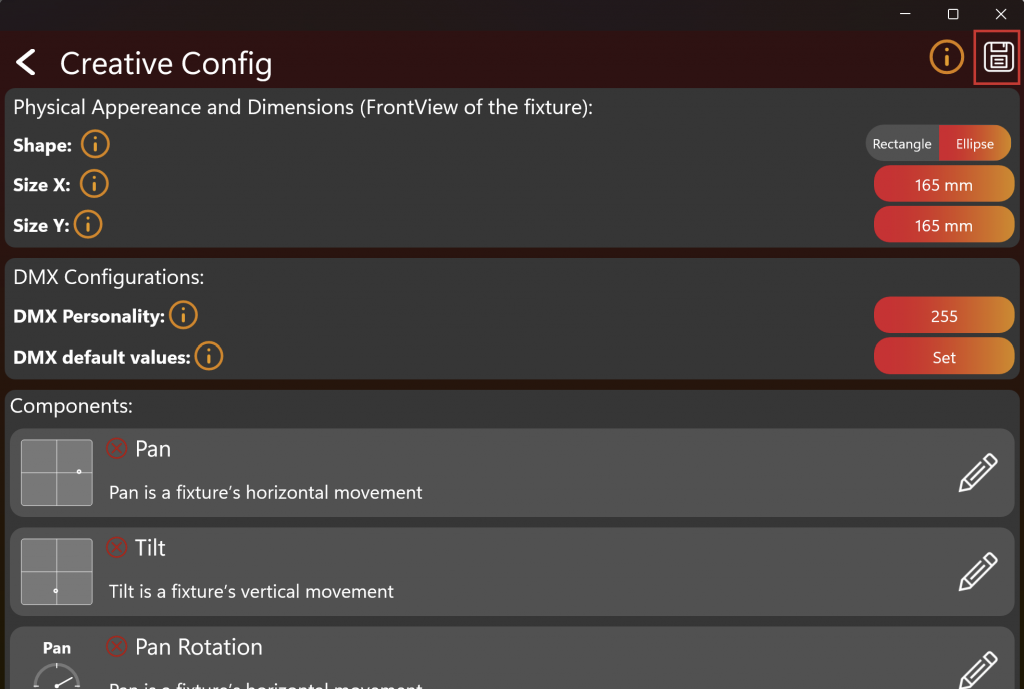
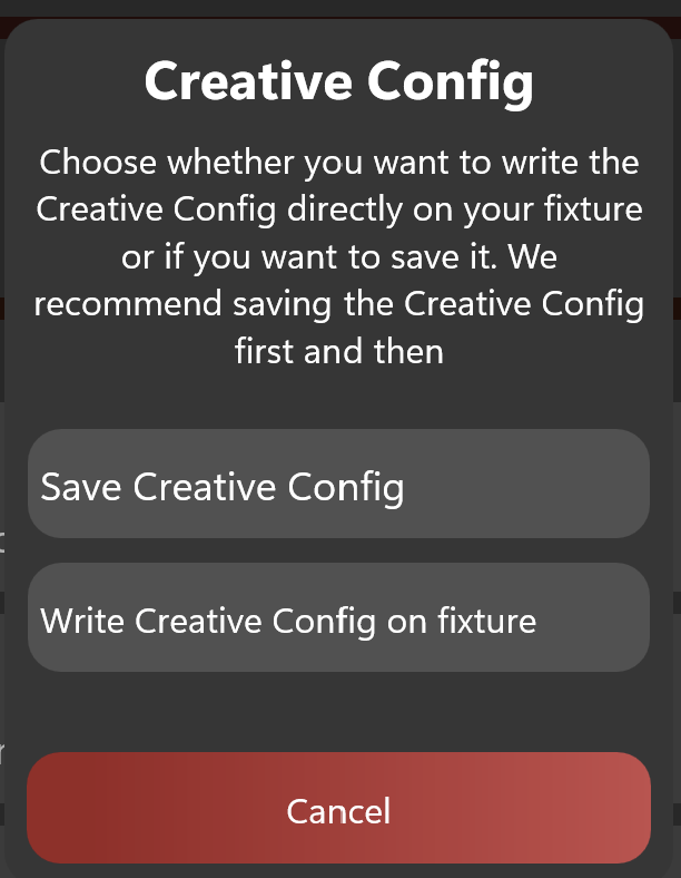
In order to upload it later to the web-service you need to save the file. The next chapter test controlling requires this to be written on the fixture.
App Control Test
75_App_Control_Test.htmlAfter enabling the Test Mode and connecting to the fixture it should look like this. To test App Control, click on "App Control Test":
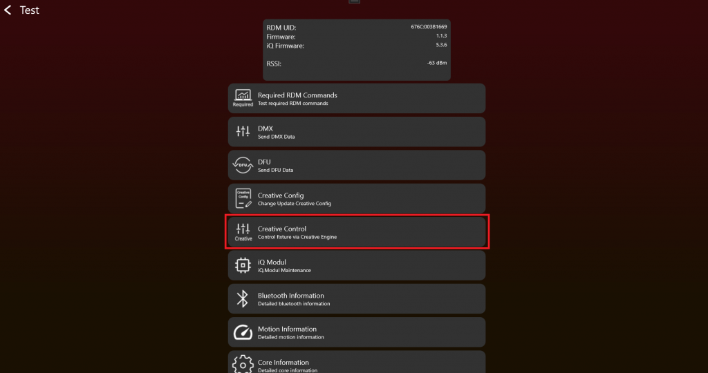
Your fixture should display only the supported components at the top. If you are able to control your fixture here, the App Control Configuration was set up correctly. If not, return to the App Control Configuration to resolve the issue.
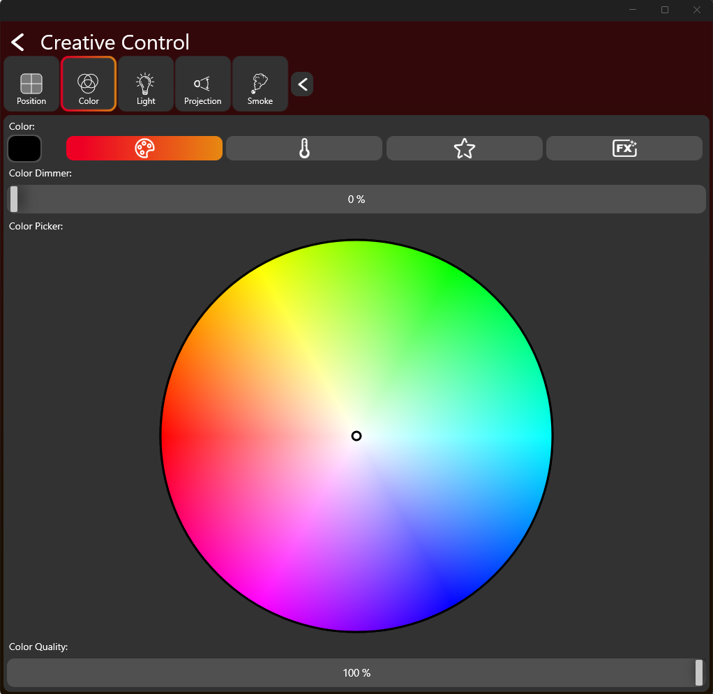
7. Firmware Update (DFU)
Goal: Enable reliable firmware updates for the fixture application and, where required, Vision-related update flows.
What to implement
- Decide whether the product supports application firmware update.
- Provide the DFU callbacks in the Vision SPI library if DFU is supported.
- Create the fixture application DFU package after the bootloader and application are prepared.
- Handle DFU start, packet, stop, and response behavior according to the DFU process.
- Keep the generated DFU file for production and release use.
- If using RDM-based DFU commands, implement the required command flow and error/status responses.
Important rules
- DFU callback implementation is not needed if DFU is not supported.
- DFU packets can have variable length and must be handled in order.
- The fixture must provide clear status/error behavior during the update process.
- Test bootloader and application firmware behavior separately before final verification.
Test immediately
- Flash the bootloader and application firmware.
- Create a DFU package and run a firmware update through the app/test workflow.
- Confirm the fixture reboots correctly and reports the expected firmware version after update.
- Test error cases such as missing packets or wrong package where possible.
- Repeat the test after changing application firmware to confirm the process is stable.
Common mistakes
- Treating DFU as finished after creating the package but before testing an actual update.
- Forgetting to save the final DFU file for release and production.
- Testing DFU only with a debug setup that differs from production firmware.
- DFU Introduction (included below)
- DFU Process (included below)
- App DFU Package (included below)
- Test DFU (included below)
- RDM DFU Command (reference link) - Optional RDM-based DFU command details.
DFU Introduction
52_Device_Firmware_Update_Introduction.htmlDFU stands for „Device Firmware Update“ and is a technology used to upgrade the firmware of embedded devices like lighting fixtures, sensors, or controllers. This process is crucial for fixing bugs, improving functionality, adding new features, and patching security vulnerabilities after the devices have been deployed.
The Vision DFU (Device Firmware Update) process involves just sending a variable sized datastream to the device. This raw datastream does not have a defined structure, which means it can work with all previous fixture DFUs. This flexibility allows any type of DFU file to be used, making it easier to update devices without needing to change the file format. To get the update data to the app a simple „.bin“ file is used. It is recommended that error checks are implemented in the data stream.
A DFU file („.bin“ file / datastream) contains the data necessary to update the firmware of an embedded device. The structure of a DFU file is designed to ensure that the firmware can be safely and effectively updated. An important aspect of this structure is the inclusion of a header, which carries specific information that helps in managing the update process. Here's how the components typically work together:
Components of a DFU Binary File with Header:
- Header: The header is a crucial part of the DFU file as it contains metadata about the firmware update. This metadata typically includes:
- Version number: Indicates the version of the firmware, helping to determine if the update is newer than the current firmware on the device.
- Device identifier: Specifies the types of devices that are compatible with the firmware, ensuring that the update is applied only to appropriate devices.
- Checksum or hash: A cryptographic hash of the firmware data, used to verify the integrity of the file after it has been downloaded or transferred, to ensure it has not been tampered with or corrupted.
- Firmware Data: This is the actual binary data that will be written to the device’s memory. It replaces the existing firmware or modifies parts of it to enhance functionality or fix issues.
DFU Process
53_DFU_Process.htmlHandling a software update is done through READ_DFU and WRITE_DFU function.
The following Interrupt lines must be used to derive the state:
- DFU_START_IRQ
- DFU_PACKET_IRQ
- DFU_STOP_IRQ
Whenever a software update is triggered, the DFU_START_IRQ goes high.
Then the fixture must get ready for receiving firmware. One of the following responses of the Fixture is required:
- 0x0: DFU_ACCEPT
- 0x1 – 0xFF: DFU_ABORT
A fixture responds by using WRITE_DFU function. The Timeout for the response is set to 20 seconds. Writing a response will disable the DFU_START_IRQ flag.
After accepting the DFU, the Vision Controller starts to send firmware packets. Each packet has a unique id which is counted upwards. Length is variable up to 200Byte. Default length is 128 Byte. packetNr is stored in Big Endian not Little Endian!
| data[0] | data[1] | data[2] | data[2] | ... | data[202] |
|---|---|---|---|---|---|
| packetNr | packetNr | data[0] | dmx[1] | ... | dmx[200] |
After reading the packet, the next packet will be transfered automatically. No extra response necessary.
If there occurs an error it is possible to abort the DFU early by writing a response greater than 0 (0x1 – 0xFF).
DFU is aborted if no packet is read for 30 seconds. It can take up to 30 seconds before the first packet arrives. Please make sure not to abort before this timeout.
After receiving the last packet, DFU_STOP_IRQ flag will go high in order to signal that all packets are transfered and DFU transmission is finished.
Now a last response from the fixture is required. The response should be one of the following:
- 0x0: DFU_SUCCESS
- 0x1: DFU_ERROR_FLASH_ERASE
- 0x2: DFU_ERROR_NOT_IN_PROGRESS
- 0x3: DFU_ERROR_CORRUPTED_HEADER
- 0x4: DFU_ERROR_CORRUPTED_IMAGE
- 0x5: DFU_ERROR_INVALID_IMAGE_VERSION
- 0x6: DFU_ERROR_NO_PREAMBLE
- 0x7: DFU_ERROR_INVALID_FIXTURE_ID
- 0x8: DFU_ERROR_UNKNOWN
- 0x9: DFU_ERROR_SIGNATURE_NECESSARY_NOT_FOUND
- 0x0A: DFU_ERROR_PACKET_TIMEOUT
- 0x0B – 0xFF: Reserved
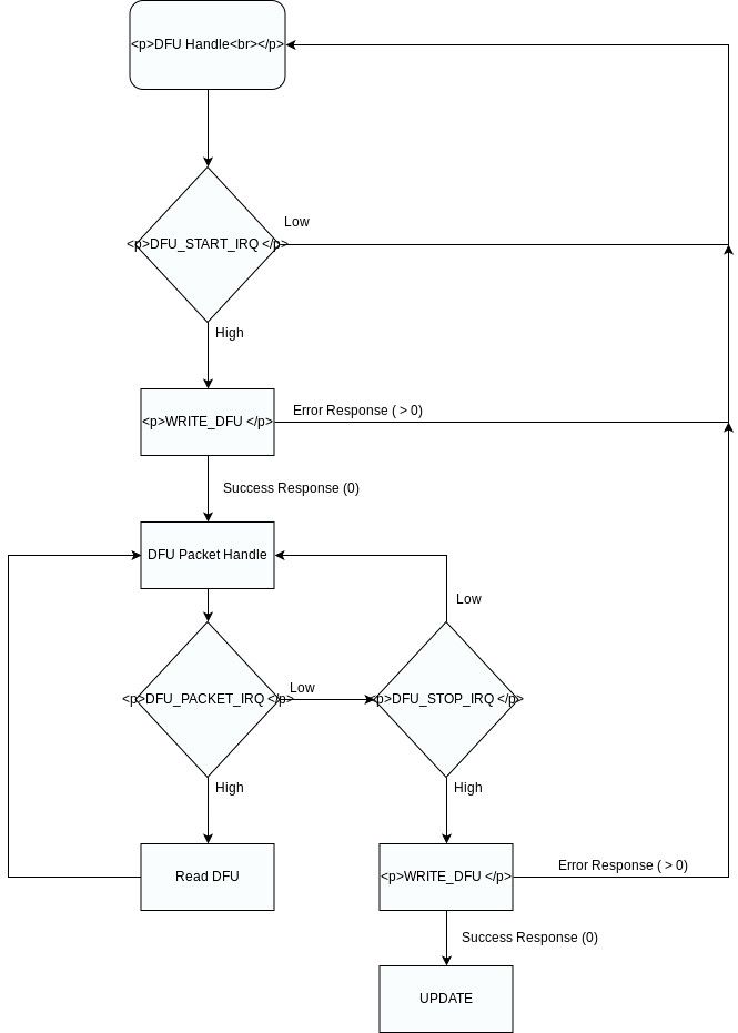
Here is an pseudo code example for receiving the data via the application firmware instead of using a boot-loader to receive the data as the example provides it:
#define DFU_BOOT_DELAY_MS     1000
#define MAX_FIRMWARE_SIZE     (256 * 1024u) // example

typedef enum
{
    DFU_STATE_IDLE = 0,
    DFU_STATE_RECEIVING,
    DFU_STATE_ERROR,
    DFU_STATE_BOOT_PENDING
} dfu_state_t;

static dfu_state_t dfuState = DFU_STATE_IDLE;
static uint32_t dfuDataCounter = 0;
static uint16_t dfuPacketCounter = 0;

static uint8_t firmwareData[MAX_FIRMWARE_SIZE]; // Just dummy, use flash to write here

static void Dfu_Reset(void)
{
    dfuState = DFU_STATE_IDLE;
    dfuDataCounter = 0;
    dfuPacketCounter = 0;
}

static void Dfu_Abort(uint8_t errorCode)
{
    vision_writeDfu(errorCode);
    Dfu_Reset();
}

static bool Dfu_StoragePrepare(void)
{
    // Erase temporary DFU flash area here.
    // Return false if erase failed.
    return true;
}

static bool Dfu_StorageWrite(uint32_t offset, const uint8_t *data, uint16_t length)
{
    // Write data to temporary DFU flash area.
    // Handle flash alignment here.
    // Return false if flash write failed.
    (void)offset;
    (void)data;
    (void)length;

    return true;
}

static bool Dfu_CheckFirmwareDataValid(uint32_t imageSize)
{
    if (imageSize == 0)
    {
        return false;
    }

    if (imageSize > MAX_FIRMWARE_SIZE)
    {
        return false;
    }

    // Recommended checks:
    // - image header valid
    // - target device / hardware ID valid
    // - firmware size valid
    // - CRC/hash valid
    // - version valid
    //
    // Final signature/security validation should also be done by bootloader.

    return true;
}

static void Dfu_StartBootloaderTimer(void)
{
    // Start one-shot timer, for example 100 ms.
    // After timeout call Dfu_BootloaderTimerElapsed().
}

static void Dfu_SetBootloaderPendingFlag(void)
{
    // Store persistent bootloader request.
    // Options:
    // - backup register
    // - retained RAM magic value
    // - flash flag
    //
    // Bootloader must check this after reset.
}


static void Dfu_BootloaderTimerElapsed(void)
{
    if (dfuState != DFU_STATE_BOOT_PENDING)
    {
        return;
    }

    Dfu_SetBootloaderPendingFlag();

    __disable_irq();

    // Optional:
    // deinit peripherals
    // flush logs
    // stop radio/SPI/UART cleanly

    NVIC_SystemReset();
}


  // Callback Implementation SPI Library ---------------------------------------------------------------------

 static void DfuFlagReceivedCallback(vision_dfu_flag_t flag)
{

	if(flag == VISION_DFUFLAG_STOP)
	{
		if (dfuState != DFU_STATE_RECEIVING)
		{
			Dfu_Abort(DFU_ERROR_NOT_IN_PROGRESS);
			return;
		}

		if (!Dfu_CheckFirmwareDataValid(dfuDataCounter))
		{
			Dfu_Abort(DFU_ERROR_CORRUPTED_IMAGE);
			return;
		}

		dfuState = DFU_STATE_BOOT_PENDING;

		// Tell sender that application-side receive/validation was okay.
		vision_writeDfu(DFU_SUCCESS);

		// Do not reset state here.
		// Wait until the response had enough time to leave the device.
		Dfu_StartBootloaderTimer();
		return;
	}
	else if(flag == VISION_DFUFLAG_START)
	{
		Dfu_Reset();

		if (!Dfu_StoragePrepare())
		{
			Dfu_Abort(DFU_ERROR_FLASH);
			return;
		}

		dfuState = DFU_STATE_RECEIVING;

		// State is valid before response is sent.
		vision_writeDfu(DFU_SUCCESS);
		return;
	}
}
static void DfuDataReceivedCallback(uint16_t packetNr,const uint8_t* buf, uint16_t length)
{
	 if (dfuState != DFU_STATE_RECEIVING)
    {
        vision_writeDfu(DFU_ERROR_NOT_IN_PROGRESS);
        return;
    }

    if (buf == NULL || length == 0)
    {
        Dfu_Abort(DFU_ERROR_INVALID_PACKET);
        return;
    }

    if (packetNr != dfuPacketCounter)
    {
        Dfu_Abort(DFU_ERROR_WRONG_PACKETNR);
        return;
    }

    if ((uint32_t)length > (MAX_FIRMWARE_SIZE - dfuDataCounter))
    {
        Dfu_Abort(DFU_ERROR_IMAGE_TOO_LARGE);
        return;
    }

    if (!Dfu_StorageWrite(dfuDataCounter, buf, length))
    {
        Dfu_Abort(DFU_ERROR_FLASH);
        return;
    }

    dfuDataCounter += length;
    dfuPacketCounter++;

}
App DFU Package
64_Custom_Firmware_App_DFU_Package.htmlHere we will explain how to get a .Bin file which can be used to update your fixture via the Vision APP. if you have followed the Custom Firmware instructions it is possible to generate this file using the following instructions:
First open the Vision App on Windows. If you are not familiar with this step please check out the following site first:
#source-66_Test_Preparations
Set the application into "Test Mode" using the following procedure. This allows to use and see development fixtures which are not registered:
- Go to "Settings" by clicking on the gear in the top:

- Click on App Settings:

- Tab on the App Software Version label (0.0.5.0) two times. After that a prompt shows up. Type in the PIN "7248". Then the Test Mode will be activated.

Now you have got the necessary functions available in the App. Go again to the settings tab.
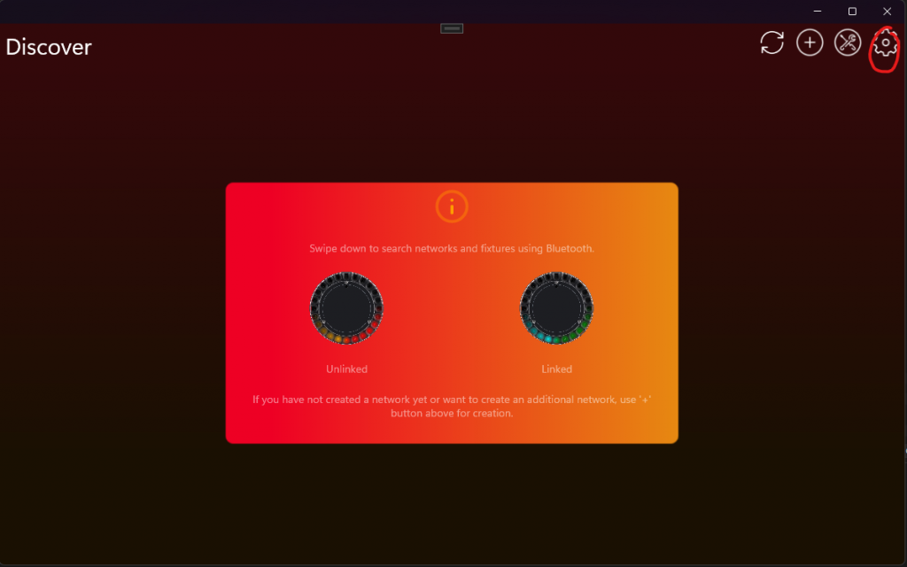
Now Developer Tools should be visible.
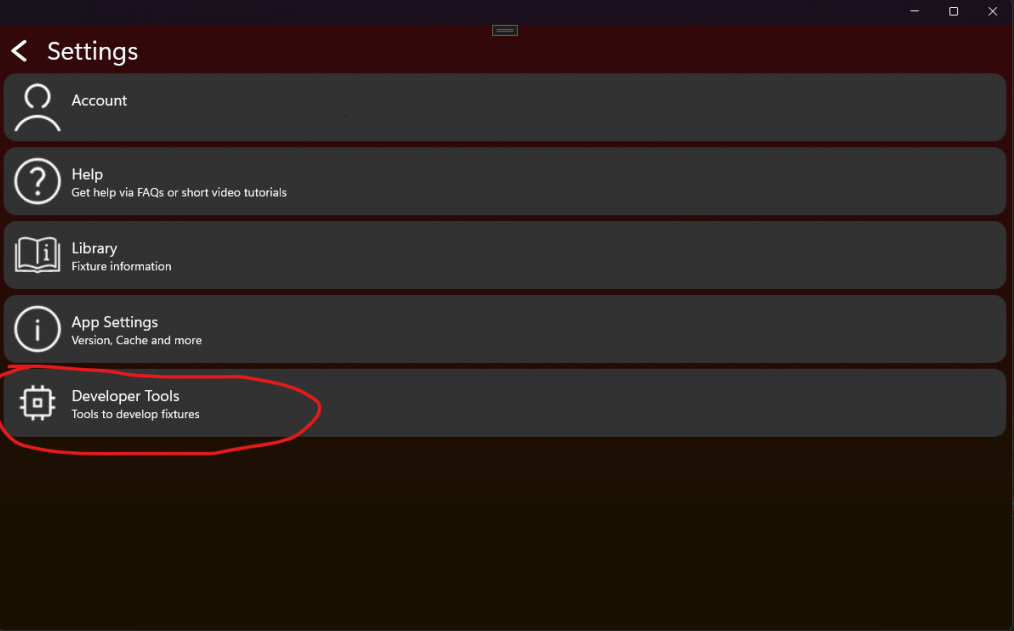
Click then on DFU File Generator:
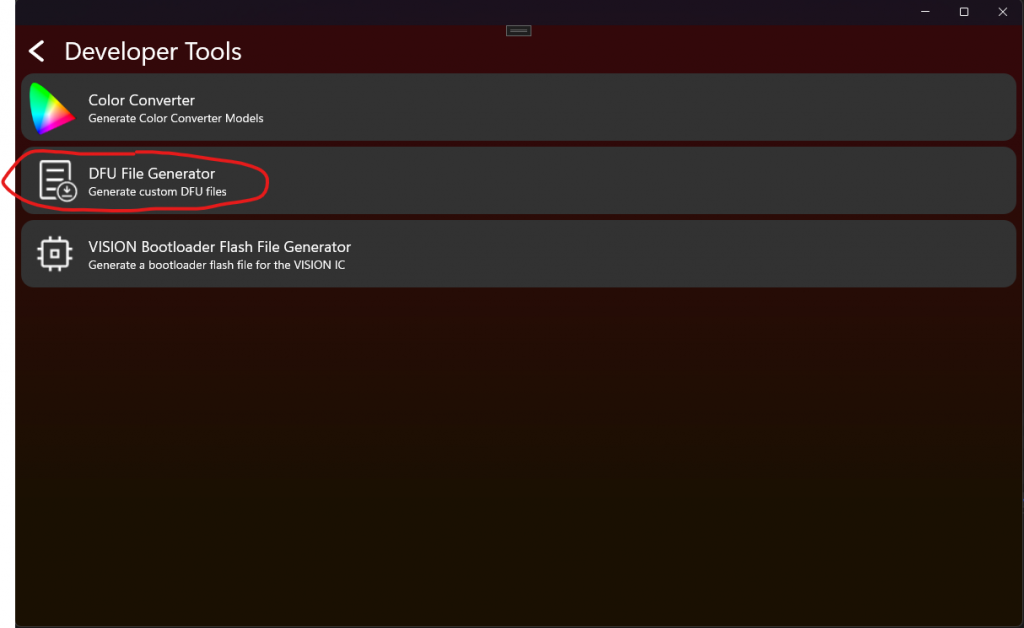
Now you are at the DFU File generator. Here you can put in your Application .Bin file, Your RDM Manufacturer Model and the RDM Device Model ID. Both in decimal and not hexadecimal.
Attention:
The DFU is secured using RDM Manufacturer and Device model id.
When you create a product you use this unique information to secure the firmware. This makes sure it is just able to be uploaded on this kind of fixture.
This is important that fixtures cannot be bricked with the wrong firmware. So make sure this is always correct.
Also put in the Firmware Version of the Application. The Vision app requires a standardized Versioning format x.x.x.x
The first is called Major. –> Indicates incompatible function to previous firmware
The second is called Minor –> Indicates added feature to previous firmware
The third is called Patch –> Indicates a bugfix to previous firmware
The forth is called Release –> Marks an Release for a public firmware verision. Always keep this 255 for public versions.
This is called Semantic Versioning https://semver.org/
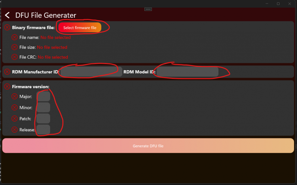
If you have followed the instructions from „Project Artery IC“ or „Project STM32 IC“ you can open Keil and build the Application Project in „ReleaseBL“ target configuration.
For Keil you have to add the following in the Target User Settings:
Add the following content in "User" command column:
fromelf.exe –bin –output .\Listings\@L.bin !L
Attention: Copying this line may is corrupted. make sure this are double hyphen.
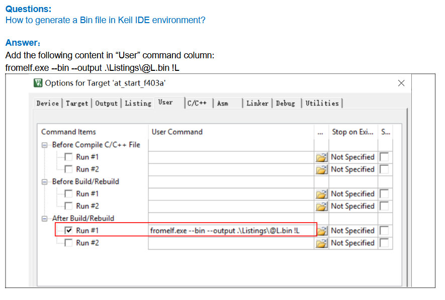
It should look like this if you have filled the data:
The Manufacturer 61450 and RDM Device Model ID 2 are only our example Values and should not be used in your product.
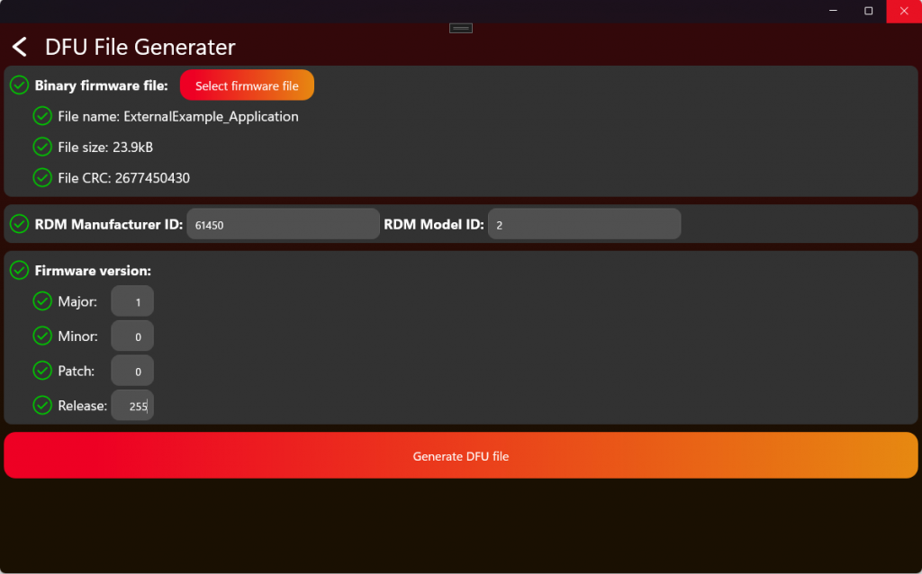
Now press „Generate DFU File“ to retrieve your file.
This file can now be used to either upload it in our webservice or manually select in the APP for update process:
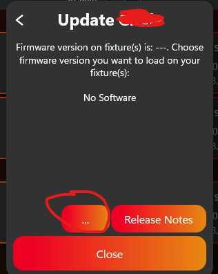
For more information about the upload process have a look at:
#source-82_Create_App_Library_Create_Fixture under Software Upload.
Test DFU
70_Test_DFU.html- After enabling the Test Mode and connecting to the fixture it should look like this. To test DFU click on „DFU“:
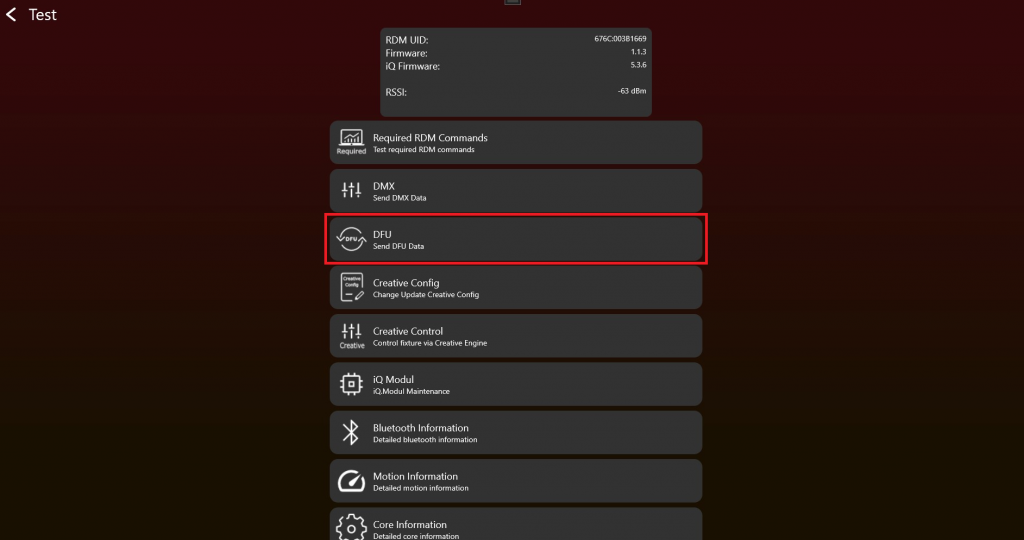
2. Simply choose a .bin file via the "Load File" button and start the DFU with "Run DFU". A progress bar and the status label will show the progress:
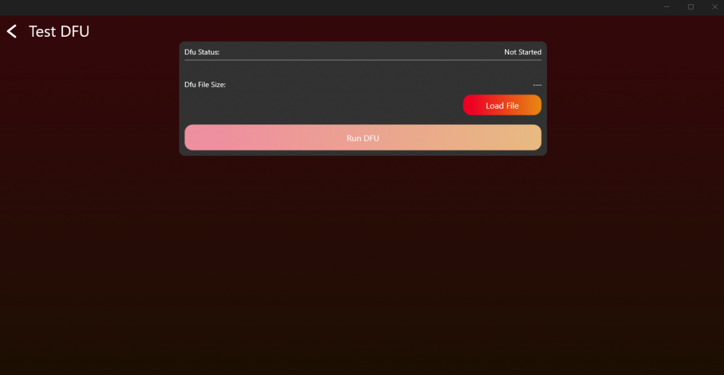
8. Optional Features
Goal: Add only the optional features that are required for the product and test them directly.
What to implement
- Decide which optional features are part of the product: NFC, IR, motion, sleep, antitheft, emergency mode, battery runtime, or others.
- Add the required hardware before relying on the feature in firmware.
- Implement the related RDM behavior and Vision custom command data where needed.
- Use the battery runtime library if the product needs runtime selection.
- Save settings that must survive power loss.
Important rules
- Optional features are only required if the product supports them.
- If a feature is implemented, it must be tested.
- Battery runtime refers to a fully charged battery and should be easy for the user to understand.
- Low-power and wakeup features must be checked together with hardware power design.
- Do not expose unsupported features to the app.
Test immediately
- Run the NFC test only if NFC is implemented.
- Run the IR test only if IR is implemented.
- Run the motion test only if a motion sensor is implemented.
- Test battery runtime selection with realistic battery levels and power consumption.
- Confirm optional feature state is correctly reported through RDM or Vision data.
Common mistakes
- Marking a feature as supported before the hardware and firmware are both ready.
- Forgetting that optional features still need production and final verification if enabled.
- Exposing a feature in the app that the fixture cannot reliably perform.
- Product Features (included below)
- Battery Runtime Library (reference link) - Only needed if the prepared runtime library is actually used.
- Test NFC (reference link) - Use only if NFC is implemented.
- Test Motion (reference link) - Use only if a motion sensor is implemented.
- Test IR (reference link) - Use only if IR is implemented.
Product Features
50_Product_Features.htmlSleep Mode
Purpose: Allows users to minimize power of fixture with wakeup possiblity from the app.
How it works:
- Users can activate sleep mode in the app
- The fixture then disables everything to minimze power like drivers, display, motors usw.
- Users can then wakeup fixture via app again. Fixtures should also wakeUp when device is reset.
Sleep Mode should last at minimum 1 Week.
Feature Battery Runtime Selection
Purpose: Allow users to optimize between brightness and battery duration.
How it works:
- The user picks how long the fixture should run (for example 2, 4 or 8 hours). The selected runtime is reached when the battery is fully charged. If the battery is only at 50%, the fixture will run for half of the selected time. This is simple and easy to understand, and does not need complex calculations. You can also show the remaining runtime to the user, so they can decide if they want to switch to a longer runtime without having to calculate it themselves.
- To reach the selected runtime, the fixture should lower its output power (brightness) based on the available battery capacity. The simplest way is to set a fixed maximum brightness that makes sure the runtime is reached.
- This is useful for events or portable use, where the light needs to last a known amount of time.
Battery Runtime Selection can be turned on and off. The setting must be saved, so the fixture remembers it after a power loss.
The runtime always refers to a fully charged battery (100%).
A good implementation limits the maximum power output of the fixture. Use the battery capacity and the current power consumption to dim the light just enough to reach the selected runtime.
How to implement it:
- Know the battery capacity, for example in Wh. If the fixture has a battery gauge, you can update this value over time as the battery ages, to keep the runtime accurate.
Example: BATTERY_CAPACITY = 100Wh - Know the power consumption of each LED. If you can measure the power live, you can use the real values instead of fixed ones.
Example:
POWER_RED = 5W
POWER_GREEN = 5W
POWER_BLUE = 5W - Calculate the maximum allowed power for the selected runtime.
MAXPOWER = BATTERY_CAPACITY / RUNTIME
Example: MAXPOWER = 100Wh / 10h = 10W - Calculate the current power used by the LEDs.
Example: ACTPOWER = POWER_RED * DIMMER_RED + POWER_GREEN * DIMMER_GREEN + POWER_BLUE * DIMMER_BLUE - Check if the power needs to be reduced:
if (MAXPOWER < ACTPOWER)
{
DIMMERCUT = MAXPOWER / ACTPOWER
} - Apply the new dimmer values to the LEDs.
NEW_DIMMER_RED = DIMMER_RED * DIMMERCUT - To show the minimum remaining runtime to the user you can just calculate:
REMAINING_RUNTIME = RUNTIME * CURRENT_BATTERY_LEVEL
For an implementation help you can refer to our runtime library which can be implemented free of charge:
./51_Battery_Runtime_Library.html
Feature Emergency Mode
Purpose: Ensure lighting is available during power outages or system failures.
How it works:
- When AC power is lost, the fixture automatically switches to battery power.
- It activates a predefined emergency lighting profile, often at reduced brightness to extend runtime.
- This mode typically complies with safety regulations (e.g., EN 60598-2-22) and may run for a minimum guaranteed duration (e.g., 1 or 3 hours).
Emergency Mode can be enabled and disabled. This setting should be saved, so if the fixture looses power it remembers its state.
If gridpower (AC) is available then it should behave as in normal operation.
Feature Anti-Theft-Mode
Purpose: Prevent unauthorized use or theft of the device.
Anti-Theft-Mode can be enabled, disabled and triggered. While Anti-Theft-Mode is enabled it should not be possible to turn off the fixture or using a user interface like a display. When Anti-Theft-Mode is triggered the fixture should signal an alarm using visual effects and or sound effects.
This feature can be fully implemented only if the fixture is battery powered. If this feature is active, all user interfaces should be locked. ( Menu locked, Button locked,..) The Vision IC has information about the current acceleration of the fixture. If that fixture is moved while in anti-theft-mode an alarm will be triggered.
- Use your internal speaker as siren (optional)
Feature Shipping Mode
Shipping Mode can only be enabled.
If the shipping mode is enabled, the fixture should turn off and cuts off battery power. The fixture can only started again through gridpower (AC), to ensure a seamless transport experince.
9. Final Verification, App Library, and Production
Goal: Confirm the complete product implementation, prepare the Vision App Library release data, and then prepare physical fixtures for production.
What to implement
- Run the implementation verification tool after each individual topic already passes its own test.
- Use the test checklist as the final confirmation for RDM, DMX, App Control, DFU, optional features, and display menu behavior.
- Create the company account and the fixture entry in the Vision App Library.
- Decide the OEM or branded fixture workflow before releasing the final RDM Manufacturer ID and RDM Device Model ID.
- Upload the required firmware, App Control Configuration, libraries, icons, and related resources.
- Request the fixture release after verification data and product data are complete.
- Purchase production licenses, flash or update Vision modules, license modules, and verify the first production sample.
Important rules
- Final verification is not the first debug step. It is the final confirmation after direct topic testing.
- If one test point fails, fix the implementation and rerun the relevant topic test before repeating final verification.
- The App Library release data must use the final firmware and final App Control Configuration.
- RDM Manufacturer ID and RDM Device Model ID must stay stable after fixture release.
- Production starts after the release data is stable and enough production licenses are available.
Test immediately
- Run the complete implementation verification tool from start to finish.
- Confirm RDM, DMX, App Control, DFU, and all implemented optional features pass.
- Check App Library data and uploaded resources against the final firmware version.
- Prepare a small production-like sample and verify flashing or update behavior.
- License the production sample and confirm the app can control it without warnings.
- Keep the final checklist result as release evidence.
Common mistakes
- Using final verification as the first time RDM, DMX, or DFU is tested.
- Mixing App Library release preparation with production licensing.
- Uploading an App Control Configuration that does not match the final firmware.
- Changing RDM Manufacturer ID or RDM Device Model ID after release.
- Licensing modules before the release data and product configuration are stable.
- Implementation Verification Tool (included below)
- Test Checklist (included below)
- Create App Library Overview (included below)
- Create App Library - Create Company (included below)
- Create App Library - OEM Branding (included below)
- Create App Library - Create Fixture (included below)
- Production Overview (included below)
- Purchase Production Licenses (included below)
- Production - Flash Vision Module (included below)
- Production - Update Vision Module (included below)
- Production - License Vision Modules (included below)
- Logo and Stickers (reference link) - Branding and sticker requirements.
- Custom Production Flash File (reference link) - Custom helper.
Implementation Verification Tool
77_Implementation_Verification_Tool.htmlImplementation Verification Tool
The Implementation Verification Tool ensures the quality assurance of all VISION products. It guarantees that every device undergoes a complete test run once its software is finalized. This test run evaluates the key functions and aspects of the product to maintain the highest quality standards.
However, this verification tool does not test all aspects of the product, and the manufacturer remains responsible for the overall quality of their product. This mode serves as an assistance tool but does not provide any guarantees.
Here is a link to a tutorial video that provides a detailed walkthrough of the Implementation Verification Tool. The video is a helpful resource but not mandatory to watch, as the documentation below is sufficient. However, the tutorial offers a more detailed step-by-step guide:
Fixture Implementation Verification Video
Test Areas:
- VISION RDM (Remote Device Management)
- VISION DMX (Digital Multiplex)
- VISION FEATURES (Product Features)
- VISION DFU (Device Firmware Update)
A fixture must pass the entire test run from start to finish. If any single test point fails, an error message will be displayed, and the test run will end automatically. The responsible developer must revise the software and can then restart the test with a new version. If all tests pass successfully, the fixture is verified.
Step-by-Step Guide
- Ensure the fixture under test meets the following prerequisites:
- Bootloader for fixture firmware flashed
- Fixture Firmware installed
- Bootloader for Vision firmware flashed
- Newest Vision firmware installed
- Activate Test Mode:
- Go to "Settings" by clicking on the gear in the top:

- Click on App Settings:
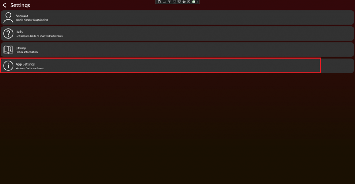
- Tab on the App Software Version label (0.0.5.0) two times. After that a prompt shows up. Type in the PIN "7248". Then the Test Mode will be activated.
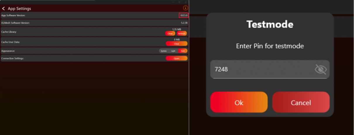
- Go back to the „Discover“ page.
- Go to "Settings" by clicking on the gear in the top:
- Scan for devices:
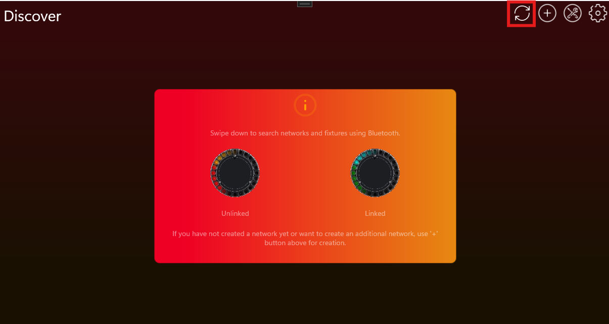
- Connect to the desired fixture by clicking on it:
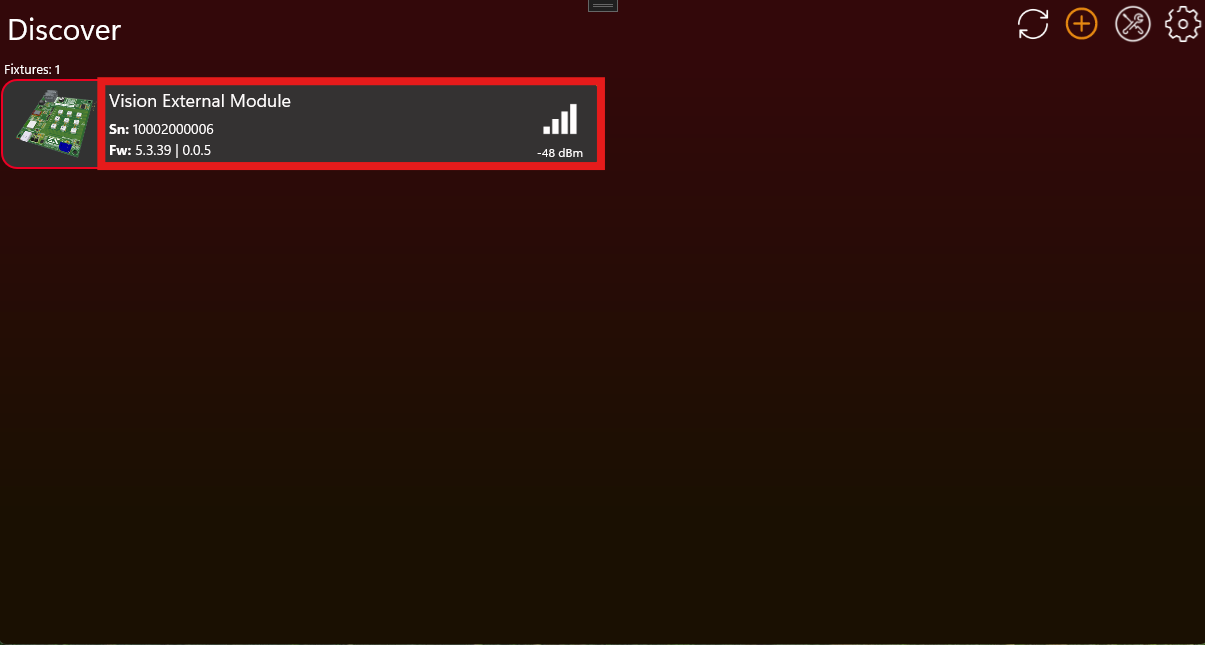
- Scroll down and click on „Verify Implementation“:
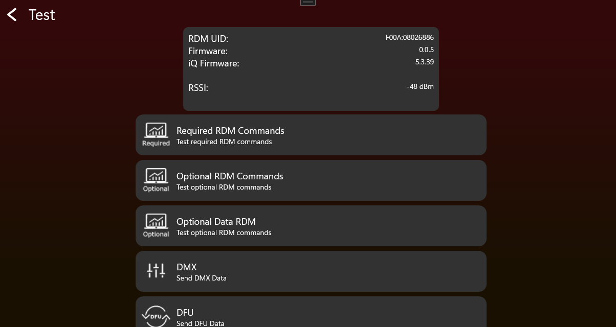 Embedded source image omitted in generated guide. Use the linked source page if this image is required.
 - A popup will appear to guide you through the entire process.
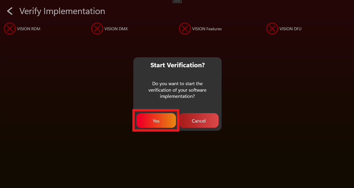
- Once all steps are successfully completed, the device will be verified.
- Download the verification certificate.
- Upload the certificate to the Visio Webservice by following those steps:
- Login to: https://server.kk-t.eu/
- Navigate to „My Fixtures“ and then click on the fixture you have verified
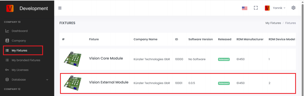
- Scroll down to „Certificates“
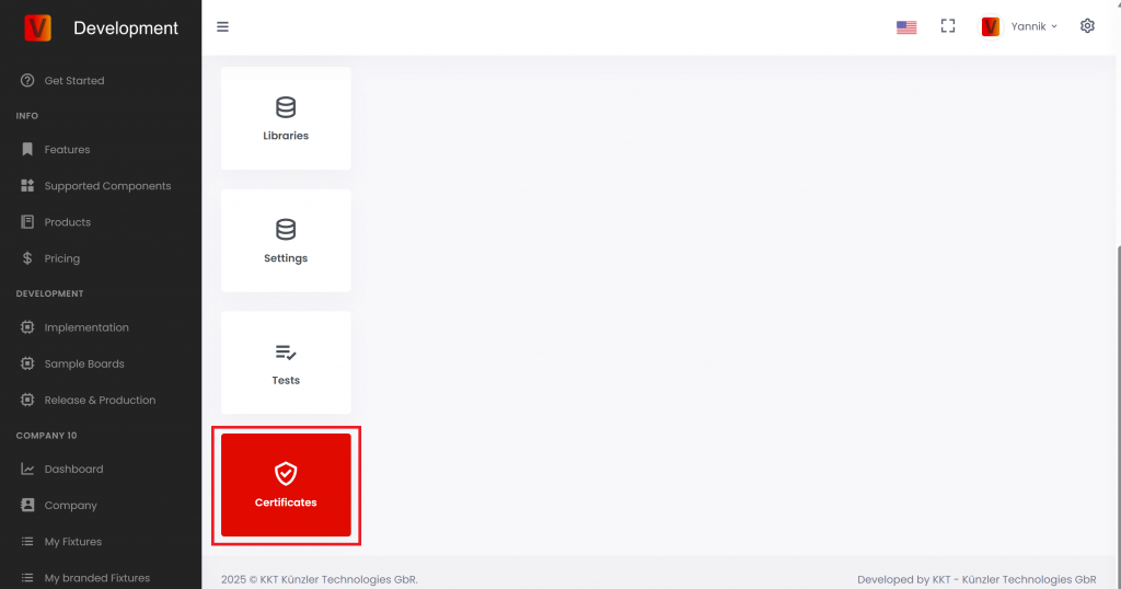
- Scroll up and click on the plus icon in the top right
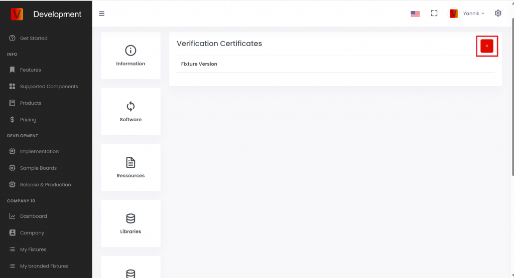
- Then upload the certificate and click „Add Certificate“.
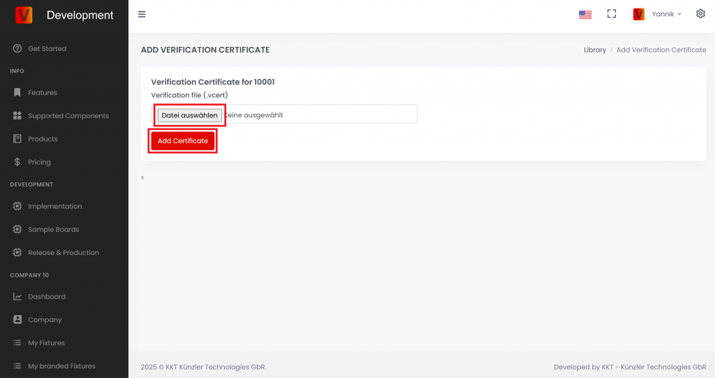
Test Checklist
78_Test_Checklist.htmlFixture Name:
Firmware Version:
DMX/RDM Test
- Factory Default to ensure fixture is in default settings
- Open Vision Control App and go into Test Mode
- Use a RDM test tool or our Vision DMX Adapter for testing
RDM
| Function | Sub Function | Passed | Comment |
|---|---|---|---|
| Test Get Device Info | Overall Look | ||
| Test Device Label | Set Get | ||
| Test Factory Defaults | Set Get | ||
| Test DMX Personality | Set Get | ||
| Test DMX start address | Set Get | ||
| Test Sensor Definiton | Get | ||
| Test Sensor Value | Get | ||
| Test Lamp Hours | Get | ||
| Test PowerCycles | Get | ||
| Test Identify | Set Get | ||
| Test Reset | Set | ||
| Power State | Set Get | ||
| Perform Selftest | Set Get | ||
| Selftest Description | Get |
Custom RDM
| Function | Sub Function | Passed | Comment |
|---|---|---|---|
| Test GET CPID VISION | Overall Look | ||
| Test Powerstate | |||
| Change DMX Address using Display, RDM | |||
| Change DMX Personality using Display, RDM | |||
| Change Input Source to Vision via Display | |||
| Test Set CPID VISION | Set Input Source | ||
| Set Input State. Therefore link the fixture in the app and unlink via Set CPID VISION Unlink | |||
| Set Emergency Mode (if it is a battery fixture) | |||
| Set Battery Runtime (if it is a battery fixture) | |||
| Set Antitheft Mode (if supported) | |||
| Test CPID Error Codes | Get | ||
| Test CPID Warning Codes | Get |
VISION Test
- Factory Default to ensure fixture is in default settings
- Open Vision Control App and go into Test Mode
- Set Fixture to VISION
RDM
| Function | Sub Function | Passed | Comment |
|---|---|---|---|
| Test Get Device Info | Overall Look | ||
| Test Device Label | Set Get | ||
| Test Factory Defaults | Set Get | ||
| Test DMX Personality | Set Get | ||
| Test DMX start address | Set Get | ||
| Test Sensor Definiton | Get | ||
| Test Sensor Value | Get | ||
| Test Lamp Hours | Get | ||
| Test PowerCycles | Get | ||
| Test Identify | Set Get | ||
| Test Reset | Set | ||
| Power State | Set Get | ||
| Perform Selftest | Set Get | ||
| Selftest Description | Get |
Custom RDM
| Function | Sub Function | Passed | Comment |
|---|---|---|---|
| Test GET CPID VISION | Overall Look | ||
| Change DMX Address using Display, RDM, Vision | |||
| Change DMX Personality using Display, RDM | |||
| Change Input Source to Vision via Display | |||
| Test Set CPID VISION | Set Input Source | ||
| Set Input State. Therefore link the fixture in the app and unlink via Set CPID VISION Unlink | |||
| Set Emergency Mode (if it is a battery fixture) | |||
| Set Battery Runtime (if it is a battery fixture) | |||
| Set Antitheft Mode (if supported) | |||
| Test CPID Error Codes | Get | ||
| Test CPID Warning Codes | Get |
Firmware Update
| Function | Passed | Comment |
|---|---|---|
| Test Firmware Update |
DMX Control
| Function | Subfunction | Passed | Comment |
|---|---|---|---|
| Test DMX Control: Vision Control Behavior == 0 | DMX start address == 1 | ||
| DMX start address == 10 | |||
| Test legacy Vision DMX Adapter behavior: Vision Control Behavior == 1 | DMX start address == 1 | ||
| DMX start address == 10 | |||
| Test App Control: Vision Control Behavior == 255 | DMX start address == 1 | ||
| DMX start address == 10 |
Display Menu Test
| Function | Passed | Comment |
|---|---|---|
| Test Input Source Vision | ||
| Test Unlink Vision | ||
| Test Vision Service Connect |
NFC Test
| Function | Passed | Comment |
|---|---|---|
| Test NFC Antenna behavior | ||
| Test WakeUp through NFC | ||
| Test RDM commands through NFC |
App Control Configuration Test
| Function | Passed | Comment |
|---|---|---|
| Test App Control Configuration | ||
| Test Shutter performance | ||
| Test Color Behavior |
Optional Tests
Button Test
| Function | Passed | Comment |
|---|---|---|
| Test Button (On/Off/Unlink) |
Battery Test
| Function | Passed | Comment |
|---|---|---|
| Test Battery |
Motion Test
| Function | Passed | Comment |
|---|---|---|
| Test Motion |
IR Test
| Function | Passed | Comment |
|---|---|---|
| Test IR |
Create App Library Overview
79_Create_App_Library_Overview.htmlThis chapter explains how to create the fixture data for the Vision Control App. This includes the company account, OEM or branding decision, fixture entry, firmware, App Control Configuration, images, and resources.
Do this before production. Production is the later step where physical modules are flashed, updated, and licensed.
What this chapter covers
- Create or request the company account on the Vision Web Service.
- Decide whether the fixture is your own product, an OEM sample, or a branded customer product.
- Create the fixture entry with the correct RDM Manufacturer ID and RDM Device Model ID.
- Upload the firmware, App Control Configuration, product images, icon, and documents.
- Request the fixture release when the implementation and uploaded data are final.
Important
The RDM Manufacturer ID and RDM Device Model ID identify the fixture type. Do not change these values after release. If these values change later, fixtures in the field may no longer be recognized as the same product.
The uploaded App Control Configuration must match the final firmware. If the firmware behavior changes, check the App Control Configuration again before release or production.
Create App Library - Create Company
80_Create_App_Library_Create_Company.htmlCreate or request your company account before creating fixtures in the Vision App Library. The same login is used for the Vision Control App and the Vision Web Service.
Open the Vision Web Service
Open https://server.kk-t.eu/ and log in with your Vision account.
If you do not have an account yet, install the Vision Control App first and create the account there:
Go to Windows Store
Go to Google Play Store
Go to Apple App Store
Use the demo company first
After login, open MY COMPANY (DEMO). The demo company shows the pages you will later use for your own company, for example Dashboard, Company, My Fixtures, and My Licenses.
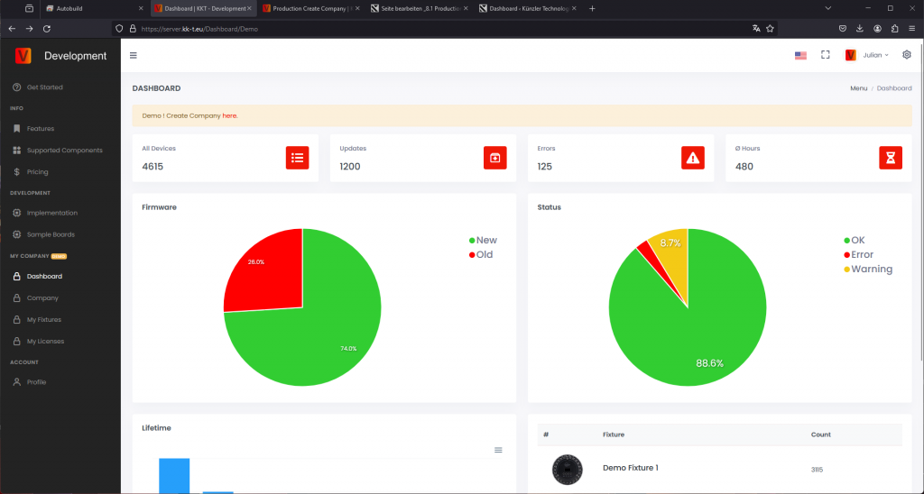
Request your company
From one of the demo pages, follow the Demo! Create Company here link. Fill in the company request carefully and use a valid company email address.
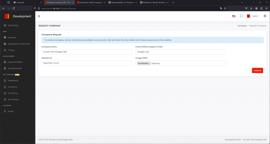
Vision Control checks the request before the company is activated. If information is missing, or if the company cannot be verified, we will contact you by email. Verification can take 2-3 business days.
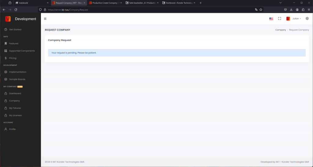
After verification, you receive an email and can create fixtures, manage release data, and buy production licenses for your company.
If one account must manage several companies, contact Vision Control or write to info@vision-cs.de.
Create App Library - OEM Branding
81_Create_App_Library_Oem_Branding.htmlThis page explains the recommended OEM and branded fixture workflow. Read this before creating the final fixture entry on the Vision Web Service.
The RDM Manufacturer ID together with the RDM Device Model ID identifies the exact fixture type. These two values cannot be changed after a fixture is released. Changing them would mean that fixtures already in the field may no longer be recognized. Descriptions, images, website URLs, resources, and names can still be changed later.
Recommended workflow
1. Development sample
Create a fixture in your company and use your own naming scheme, your RDM Manufacturer ID, and your RDM Device Model ID. This fixture is used for internal development, demonstrations, and customer samples. It does not need to be visible publicly in the app.
RDM Manufacturer: your company Manufacturer ID
RDM Device Model ID: your fixture-specific Device Model ID
Example with the Vision Core Module:
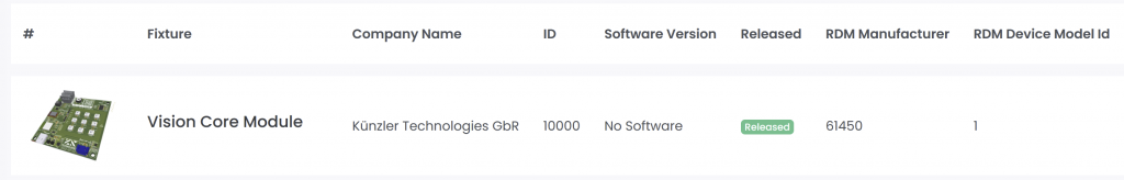
When the sample is finished and verified, request a release on the fixture page. Until release, the fixture remains internal and only authorized accounts can access it.
2. Customer sample
After the sample is released, ship it to the customer for testing. If the customer wants a branded fixture, continue with the branded production fixture. If no branding is required, you can continue directly with production.
3. Branded production fixture
For a branded product, adapt the firmware and product data to the customer's requirements. The released product should use the brand's final RDM information if the brand needs to own the fixture identity.
RDM Manufacturer: brand's Manufacturer ID
RDM Device Model ID: brand's fixture-specific Device Model ID
Create a separate fixture on the server with the brand's final product information.
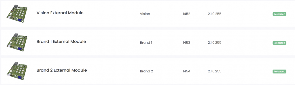
After the branded fixture entry is ready, you can share access to the fixture with the brand so they can maintain product data or release information if required.
Create App Library - Create Fixture
82_Create_App_Library_Create_Fixture.htmlCreate the fixture entry after the company account exists and the final fixture identity is clear. The fixture entry is the App Library record used by the Vision Control App to recognize the product and load the correct app data.
Before you start
- Final RDM Manufacturer ID.
- Final RDM Device Model ID.
- Fixture name, brand name, product description, website, and support information.
- Serial number format used by the fixture.
- Final or release-candidate firmware file.
- Final App Control Configuration that matches the firmware.
- Fixture image, app icon, and optional documents such as manual, DMX chart, or technical data sheet.
Important: the RDM Manufacturer ID and RDM Device Model ID must stay stable after release. These two values are how Vision identifies the fixture type.
Open My Fixtures
Log in to the Vision Web Service, open your company, and go to My Fixtures.
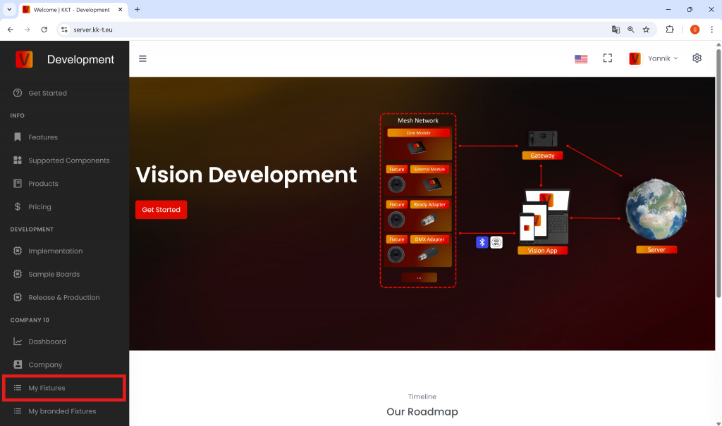
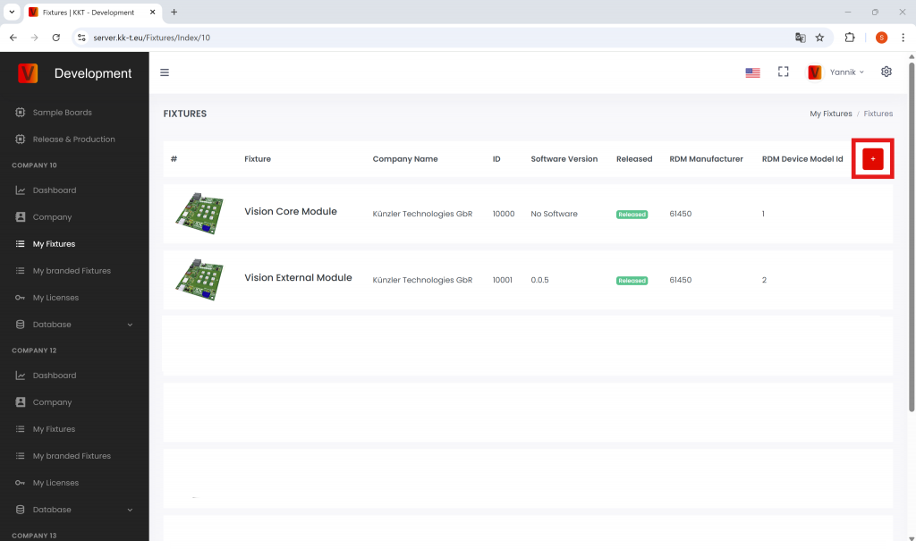
Create the fixture
Click the plus button to create a new fixture. Fill in the product identity carefully.
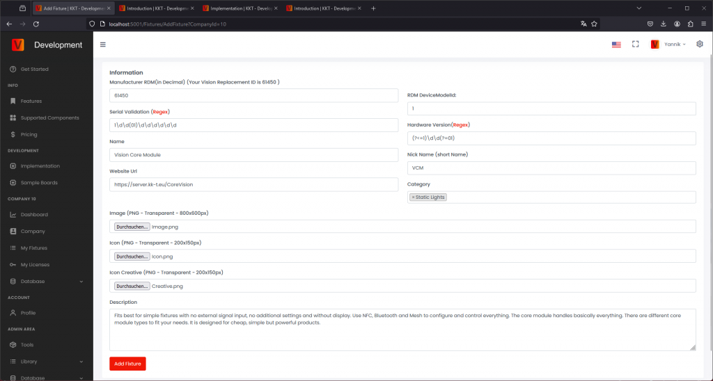
- RDM ESTA Manufacturer ID: enter the decimal value. If your value is written in hexadecimal, convert it to decimal first. If you are not an RDM manufacturer, use your assigned Vision replacement ID.
- RDM Device Model ID: enter the decimal value of the fixture model ID.
- Serial number validation: enter the regular expression used to validate fixture serial numbers. If there are no special requirements, use the simple numeric format already recommended by Vision Control.
- Product information: add the user-facing name, brand, description, website, and support information.
After saving, the fixture appears on the My Fixtures page. New fixtures are created as draft and are not released to normal users yet.
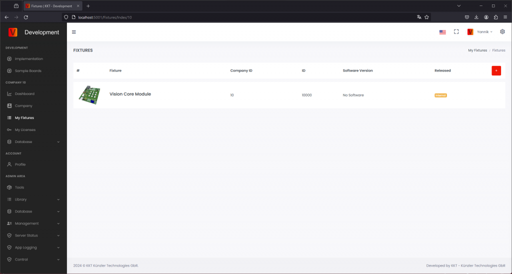
Add image and icon
The fixture image and icon are shown in the app. They should make the product easy to recognize.
- Image: upload a clear product image.
- Icon: use a transparent 200 x 150 px icon without active light output.
- App Control icon: mark the controllable light area. Older pages or screenshots may call this Icon Creative.
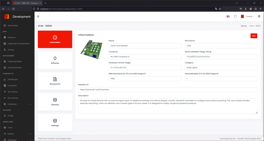
Upload firmware
Open the Software section and upload the firmware file for the fixture. Add clear release notes so the customer can understand what changed.
- Use the versioning format expected by the Vision Web Service.
- Only release firmware that was tested on the real fixture.
- Keep draft firmware internal until it is ready for release.
When the firmware is ready for users, change it from draft to release.
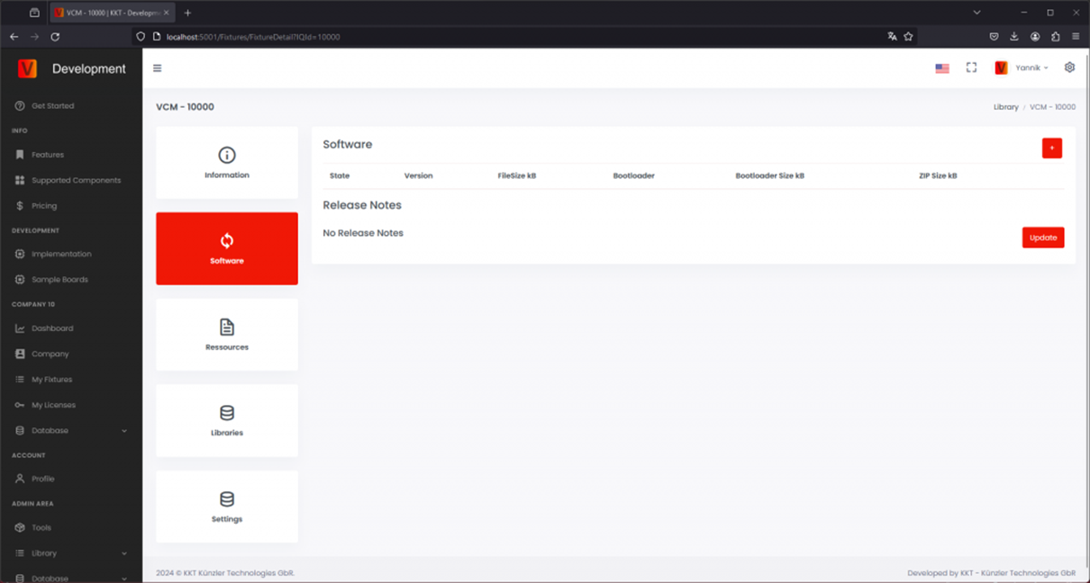
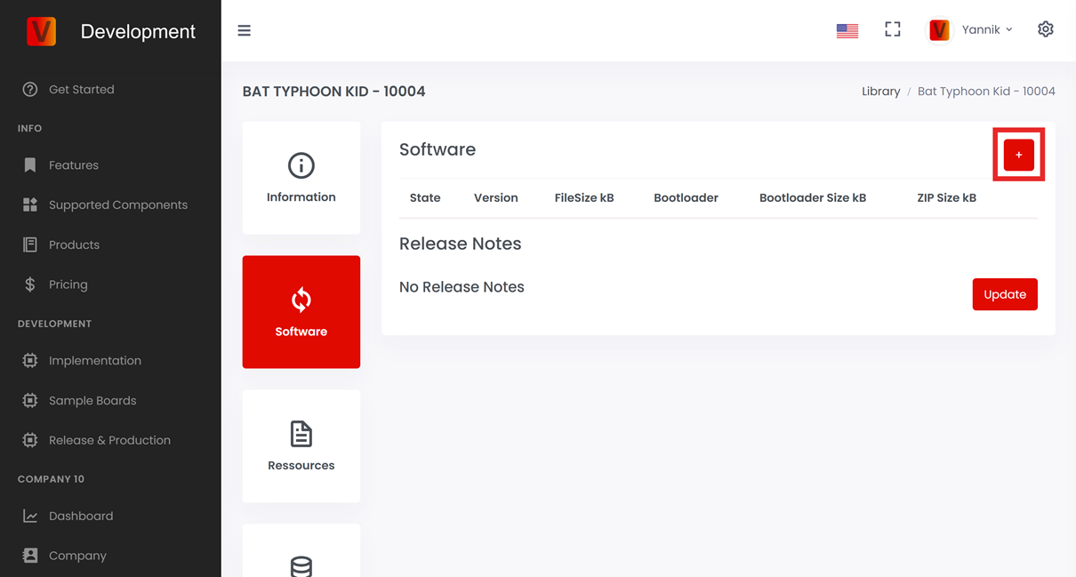
Upload resources
Upload customer-facing documents in the resources area. Typical resources are the user manual, DMX sheet, safety information, technical specification, or service documents.
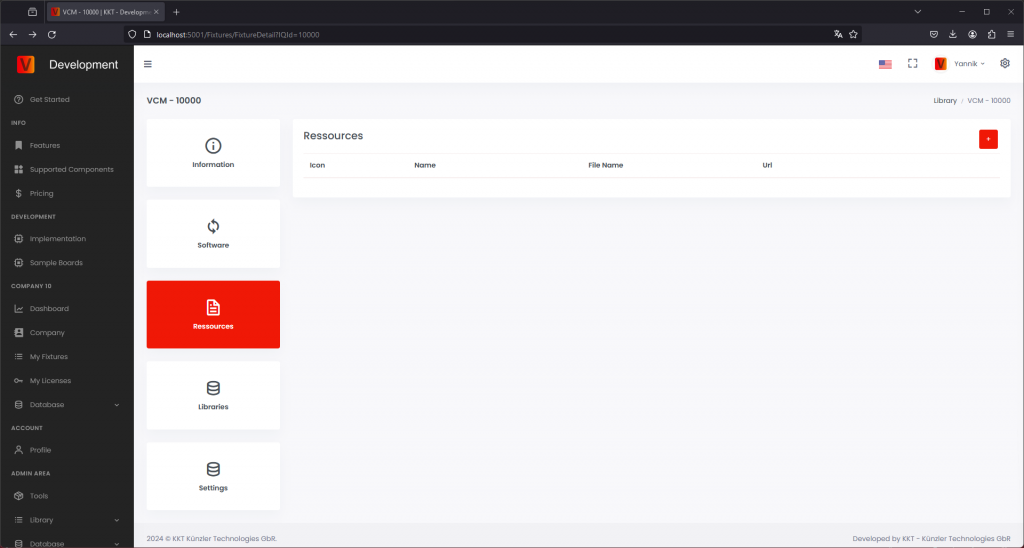
Upload App Control Configuration
Upload the final App Control Configuration created and tested during implementation. This configuration must match the final firmware behavior. If the firmware behavior changes, check whether the App Control Configuration must also be updated.
Legacy naming: App Control Configuration was previously called Creative Configuration or Creative Config in older app versions, screenshots, URLs, and filenames.
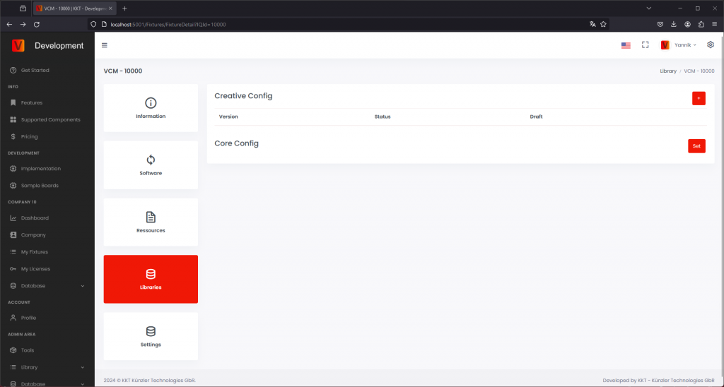
If several firmware versions use the same configuration, they can reference the same App Control Configuration. If a new firmware changes the DMX layout or App Control behavior, upload a new configuration and assign it to the matching firmware version.
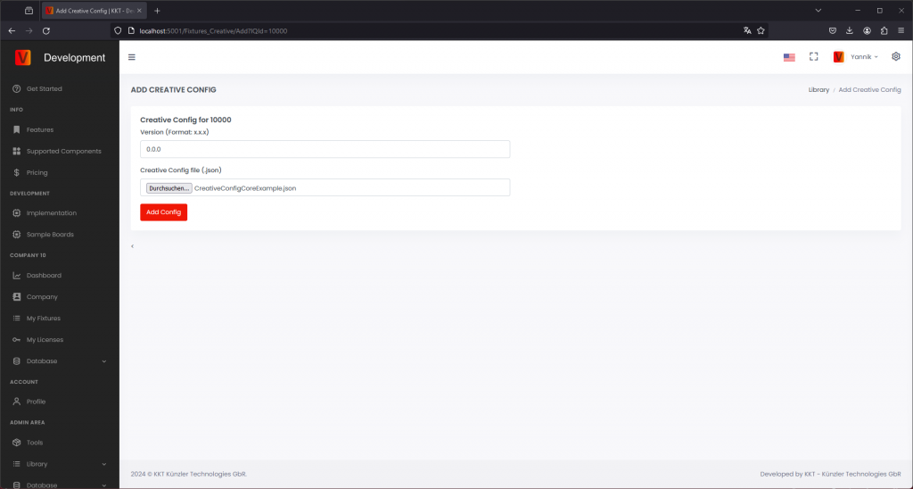
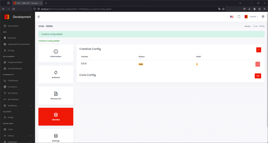
Check release information
Before requesting the release, check all information that will be visible or used by the Vision Control App.
- Fixture name, brand, description, website, and support contact.
- RDM Manufacturer ID and RDM Device Model ID.
- Firmware version and release notes.
- App Control Configuration assigned to the correct firmware version.
- Fixture image, icon, and App Control icon.
- Resources such as manual, DMX chart, technical data sheet, or safety information.
The RDM Manufacturer ID and RDM Device Model ID cannot be changed after release. Other product information can be updated later, but it should still be checked carefully before release.
Request release
Request the fixture release only after the real fixture was tested with the final firmware, final App Control Configuration, and final product data. Upload the requested verification information and, if required, a video that demonstrates the fixture functionality.
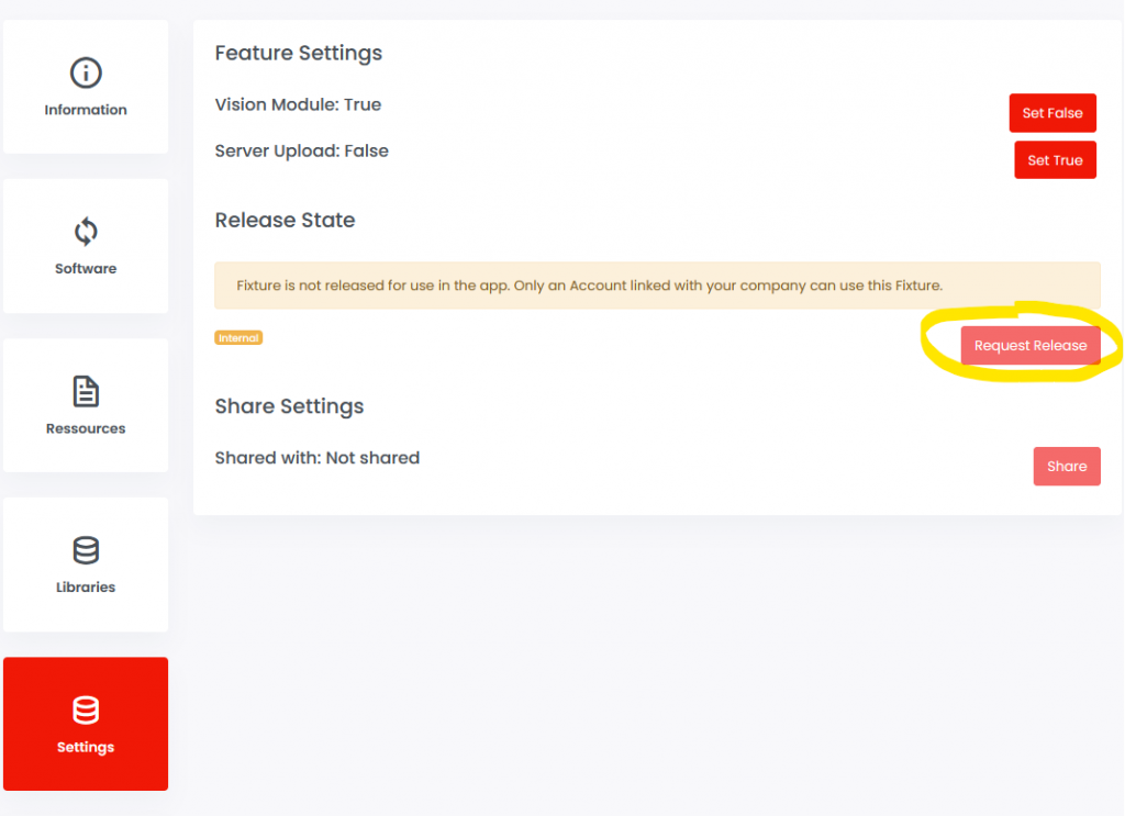
After release approval, continue with the production chapter: purchase production licenses, flash or update Vision modules, license modules, and verify the first production sample.
Share fixture access
If you manufacture the fixture as an OEM and another company owns the brand, share fixture access with that company after the fixture entry is ready. The brand can then maintain product data or release information according to the agreed workflow.
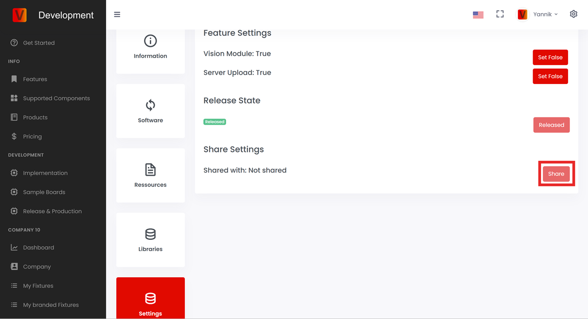
Production Overview
82_Production_Overview.htmlProduction starts after the fixture implementation is verified and the App Library data is prepared. In production, every physical fixture must receive the correct Vision firmware/data, the correct App Control Configuration, and a valid production license.
Before production
- The fixture firmware is final or production-approved.
- The App Control Configuration matches the final firmware.
- The fixture entry exists in the Vision App Library.
- The fixture was verified with the implementation verification tool.
- Production licenses are available for the company.
- The production station can flash, update, and test the Vision module.
Production flow
- Purchase production licenses: make sure enough licenses are available before building a batch.
- Flash the Vision module: program the Vision module with the correct bootloader or production flash file for the selected hardware module.
- Update the Vision module: if the production flash file does not already contain the final app data, update the module with the final App Control Configuration in the Vision Control App.
- License the Vision module: activate the production license for each fixture through the License Manager.
- Verify the first production samples: check discovery, connection, App Control, DMX Control, RDM data, firmware version, and optional features.
- Finish market preparation: apply required Vision logo or sticker information and complete certification-related tasks.
Flash file or app update
For small batches or development samples, it is often fine to update App Control Configuration through the app. For larger production runs, a production flash file can reduce manual steps because the required Vision data is already included during flashing.
If the product uses custom hardware or a custom firmware workflow, also check the custom production flash file documentation.
Production sample check
Always test at least the first units of a production batch with the final app release data. A sample that was only tested with development data is not enough for production approval.
Purchase Production Licenses
85_Purchase_Production_Licenses.htmlProduction licenses must be available before fixtures can be licensed for normal customer use. Buy licenses from the company account that owns the fixture production.
Open My Licenses
Log in to the Vision Web Service at https://server.kk-t.eu/, open your company, and go to My Licenses. The page shows free and already used licenses. Click the shopping cart to buy more licenses.
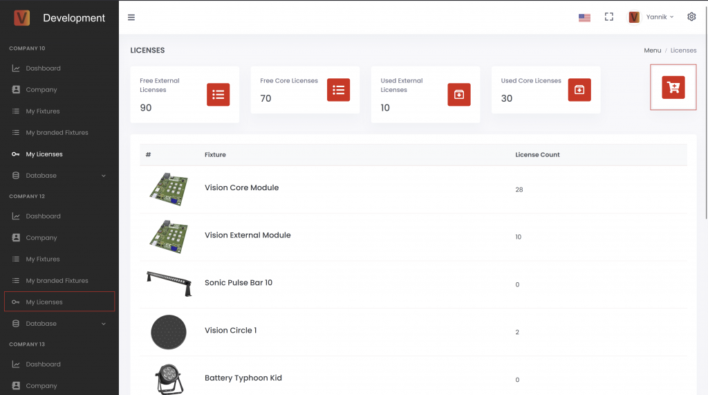
Choose license type and quantity
Select the required license type and enter the quantity. The price is calculated automatically according to the current pricing scheme. For contract pricing or larger quantities, contact the Vision Control team before ordering.
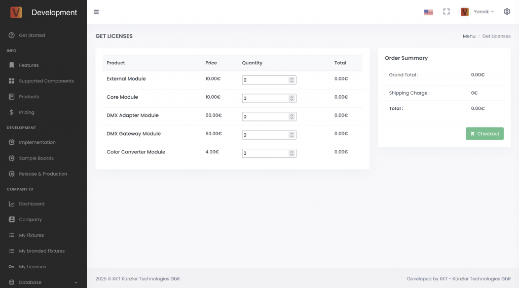
Checkout
Enter the company and payment information. Use a clear address format, for example:
Example Company Inc
Street and house number
ZIP code and city
Country
If anything is unclear, contact Vision Control before submitting the order.
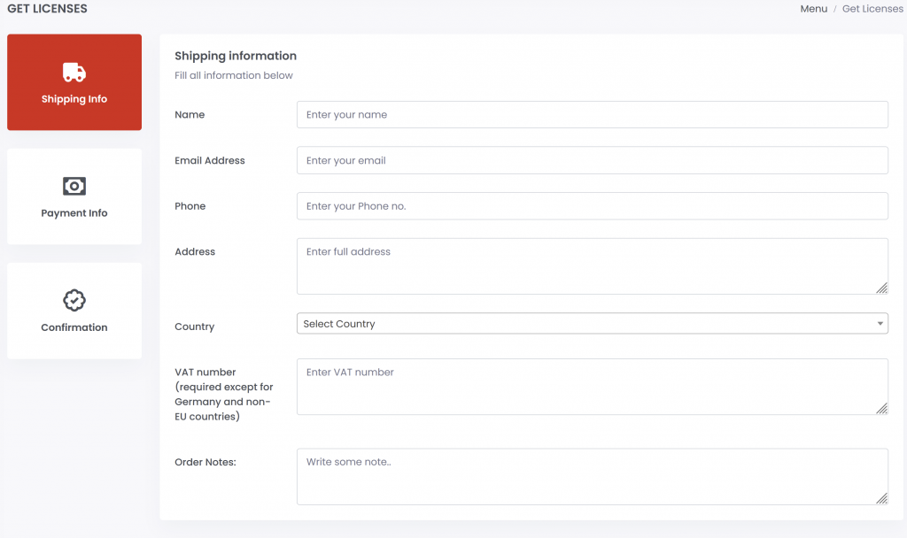
After ordering
After the order is successful, the company page shows the order overview. You can view and download invoices there. The purchased licenses can then be used in the production licensing step.
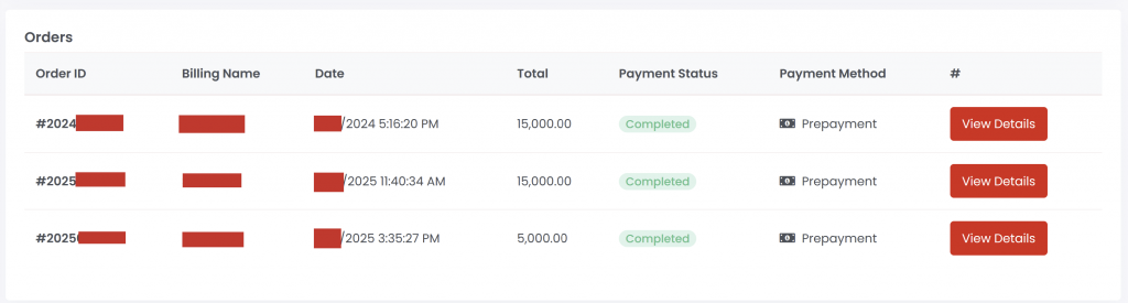
Production - Flash Vision Module
82_Production_Flash_Vision_Module.htmlThis page describes the production flashing step for the Vision module. In the standard production flow, flashing writes the required Vision bootloader to the Vision IC.
The fixture application firmware is normally not flashed in this step. The fixture firmware should be installed or updated through the firmware update procedure so that the bootloader and update process are verified correctly.
For faster production, it is optional to generate a fixture-specific bootloader flash file that contains the Vision bootloader together with the final App Control Configuration. This reduces manual app steps later in production.
If the Vision module already contains the correct bootloader and the final App Control Configuration, continue with the licensing step instead.
Flash bootloader
Download the correct Vision bootloader from the Vision Firmware page. Choose the file that matches the Vision hardware module used in the fixture.
- Select the correct bootloader file for the Vision module.
- Erase the Vision IC before flashing so the MBR is erased correctly.
- Flash the bootloader with the corresponding flash tool for the module.
- Power the fixture and confirm that the Vision module can be discovered by the Vision Control App.
Optional bootloader + App Control Configuration
A production flash file can include the Vision bootloader data and the final App Control Configuration. This can reduce manual app steps during production. The exact file depends on the Vision hardware module and the final fixture configuration.
The Vision Control App includes a developer tool for generating a Vision bootloader flash file. This is optional and mainly useful when production should preload the App Control Configuration into the Vision module.
- Enable developer tools in the app settings.
- Open Developer Tools.
- Open VISION Bootloader Flash File Generator.
- Select the Vision IC or module type used in the fixture.
- Select the fixture from the App Library.
- Check optional settings only if they are required for the product.
- Generate the Vision bootloader flash file.
- Flash the generated file to the Vision IC with the approved production programmer, for example J-Link.
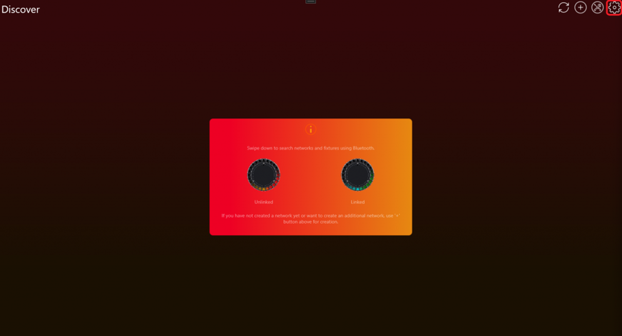
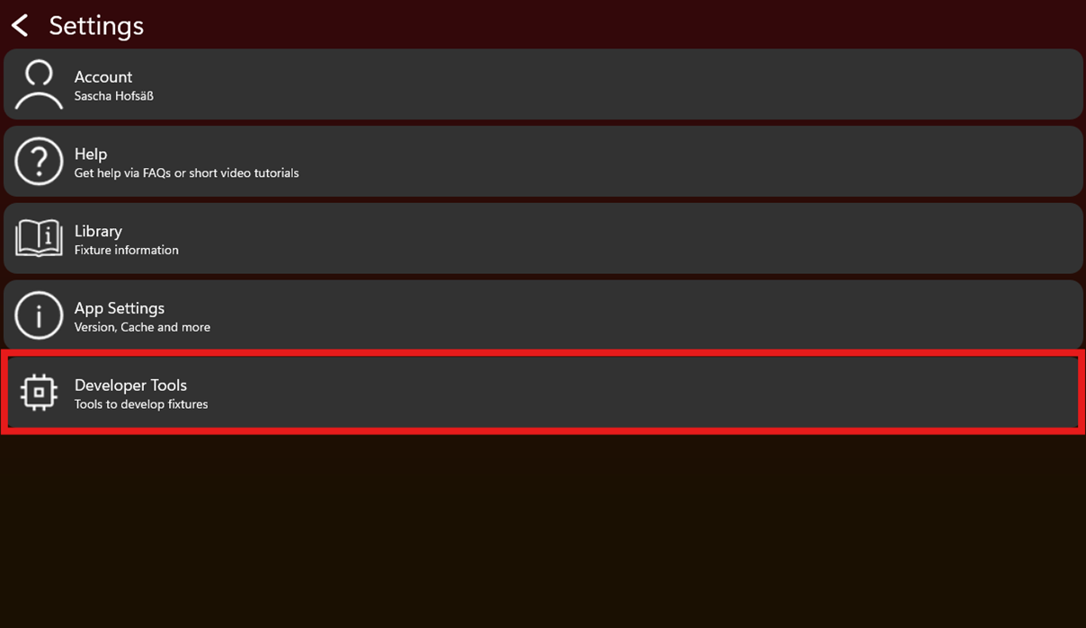
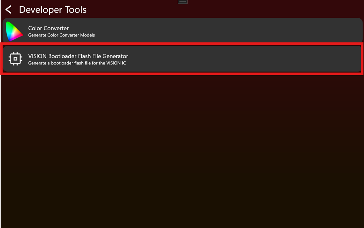
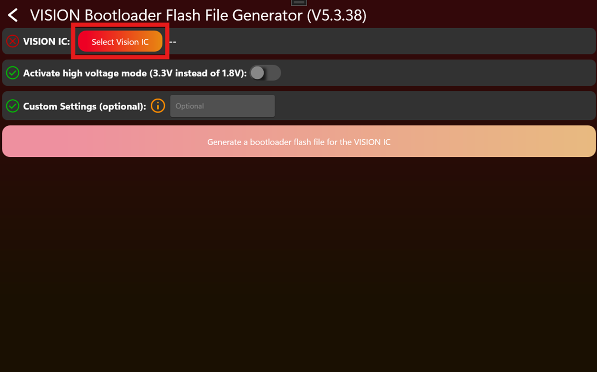
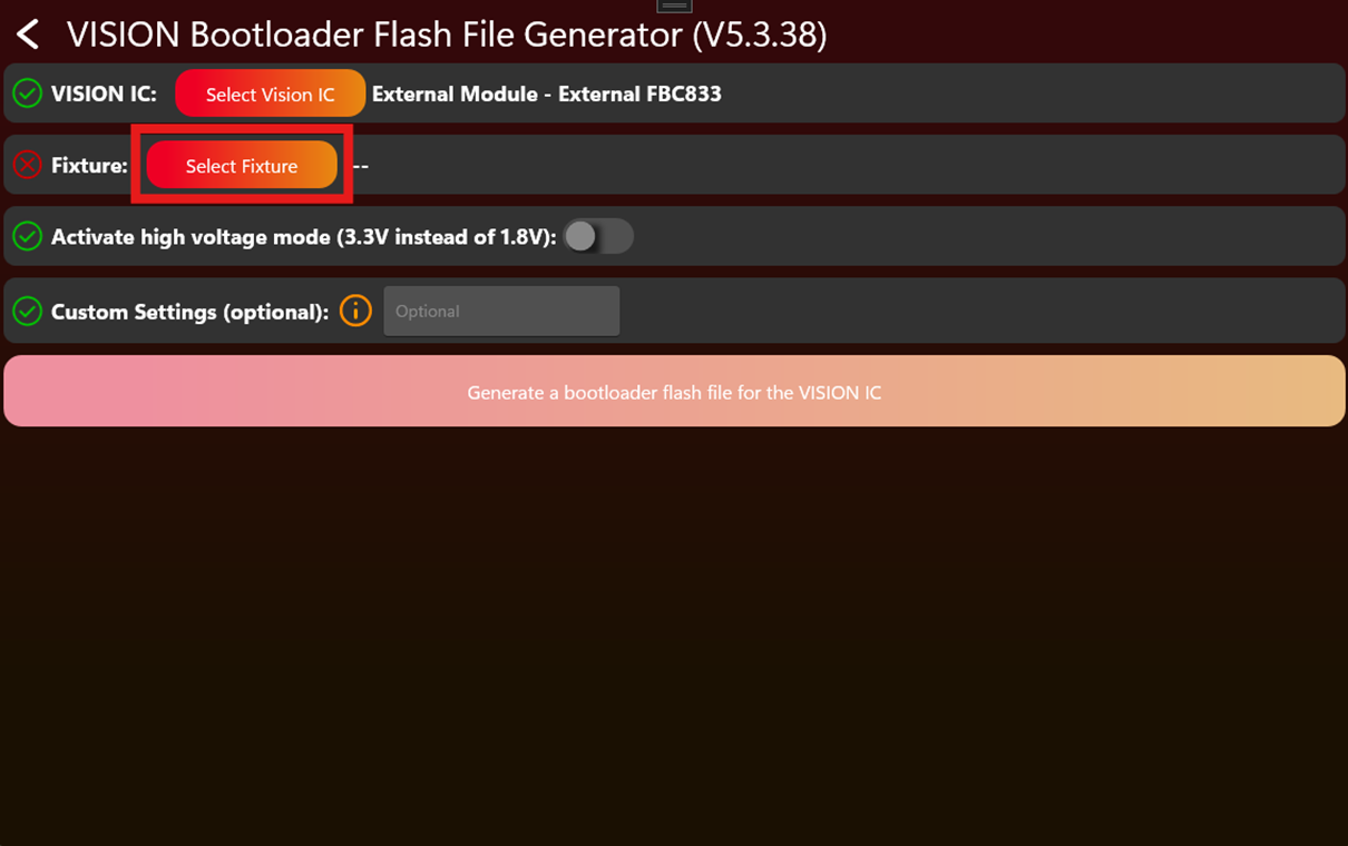
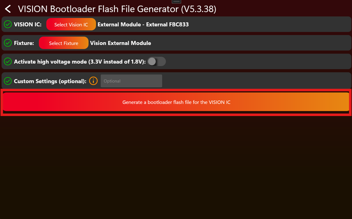
After flashing
Power the fixture and scan it with the Vision Control App. The fixture should appear as Vision Bootloader and be ready to receive the firmware.
Production - Update Vision Module
82_Production_Update_Vision_Module.htmlThis page describes how to update a Vision module with the final App Control Configuration. Use this step when the fixture was flashed without the final app data, or when the App Control Configuration was changed after the module was programmed.
When this is required
- The production flash file did not include the final App Control Configuration.
- The App Control Configuration was updated after flashing.
- A development module must be converted to the final released fixture data.
- The app shows that the fixture requires an App Control Configuration update.
The App Control Configuration must match the final firmware. If firmware and App Control Configuration do not belong together, App Control can behave incorrectly.
Update with the Vision Control App
- Power the fixture and open the Vision Control App.
- Scan for fixtures.
- Open the tools icon with the red badge.
- Open App Control Configuration Manager.
- Select the fixture or use Update all for all detected fixtures that need the update.
- Wait until the update is finished.
- Restart the fixture if the app or fixture behavior requires it.
- Scan again and confirm that no App Control Configuration update is pending.
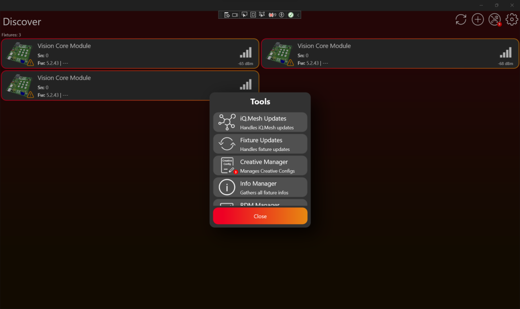
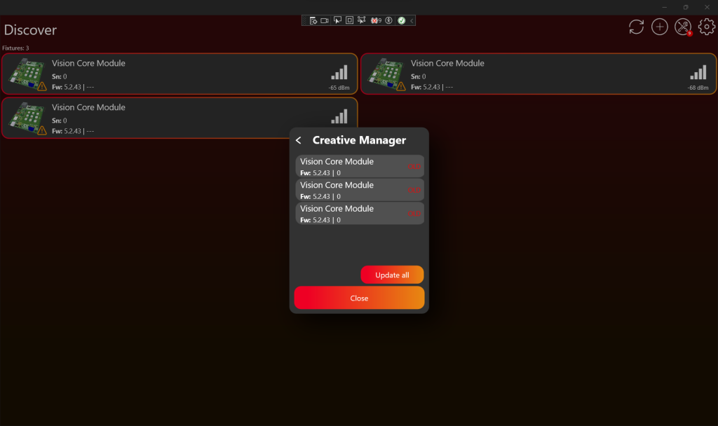
After the update
Test the fixture directly in App Control. Check that the shown controls match the product and that every configured function reacts correctly. After this check, continue with production licensing.
Production - License Vision Modules
83_Production_License_Vision_Modules.htmlThis page describes the production licensing step. Licensing activates a production license for each physical fixture. Do this after the fixture is implemented, verified, registered in the Vision App Library, and prepared with the correct Vision data.
Check license availability
Open https://server.kk-t.eu/, log in, open your company, and go to My Licenses.
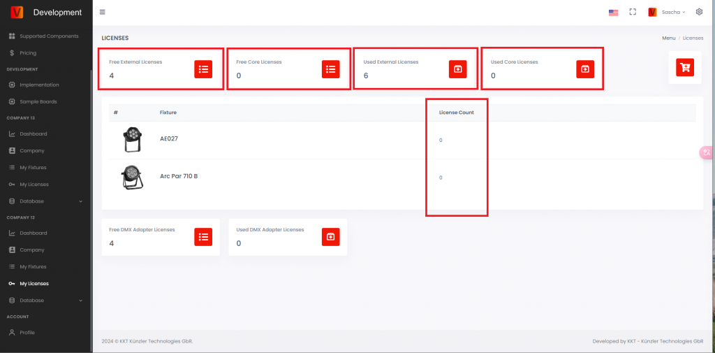
- Free External Licenses: purchased External Vision licenses that are not used yet. This value must be greater than 0 before licensing a new External Vision fixture.
- Free Core Licenses: purchased Core licenses that are not used yet.
- Used External Licenses: External Vision licenses already activated for fixtures.
- Used Core Licenses: Core licenses already activated for fixtures.
- License Count: number of licenses used by a specific fixture type.
Find unlicensed fixtures in the app
Open the Vision Control App and scan for fixtures. An unlicensed production fixture can be shown with a warning. The warning means the fixture is detected, but it cannot be used normally until a license is activated.
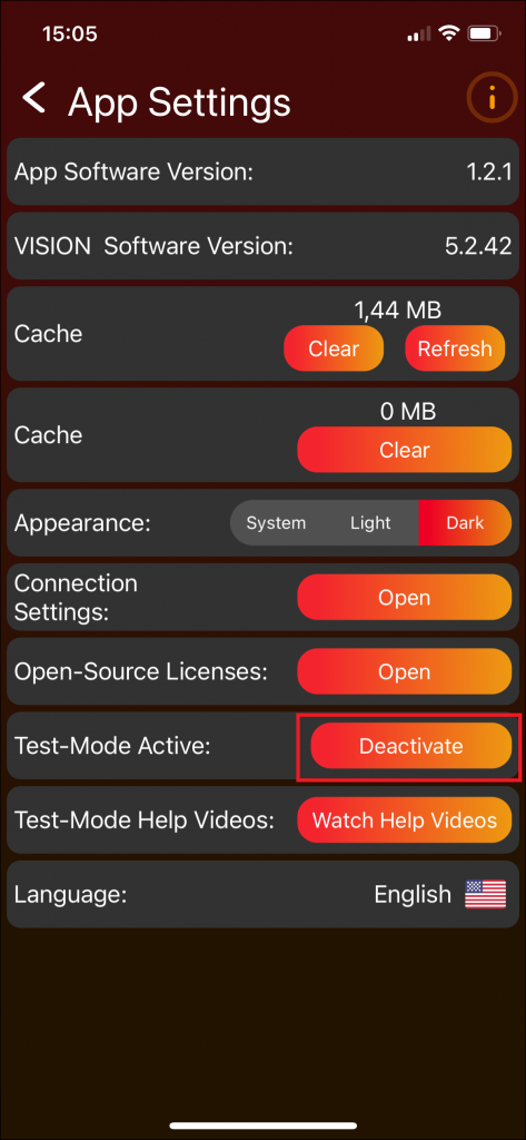
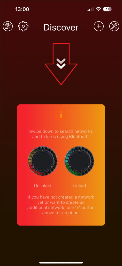
License the fixtures
- Open the tools area in the Vision Control App.
- Open License Manager. A red badge can indicate fixtures waiting for licensing.
- Check that the fixture is shown as licensable.
- Use License all if all listed fixtures should be licensed.
- Wait until the app confirms the licensing result.
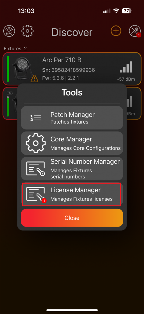
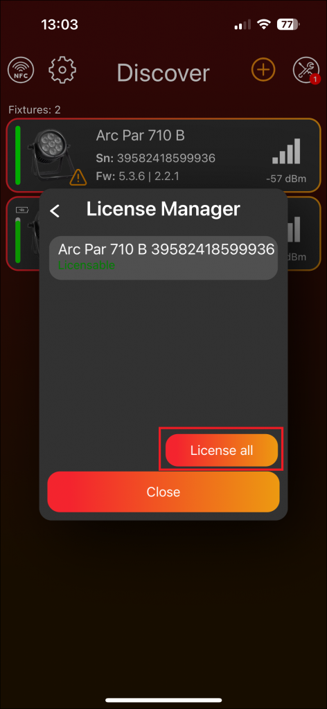
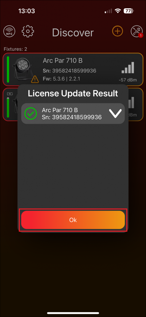
Verify the license
After licensing, the fixture should no longer show the unlicensed warning and can be controlled with the Vision Control App. On the Vision Web Service, the free license count is reduced and the used license count is increased.
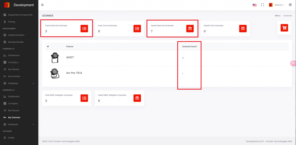
Open the fixture license details to see the licensed fixtures with serial number, RDM ID, and related information.